Page created on 11/07/2025.
Other body fittings (continuing)
Buffers
The first buffers I received, made of nickel silver, were warped. AMF87 kindly replaced them. But these buffers have a plunger that is much too large compared to the real thing. Judge for yourself:
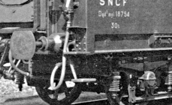
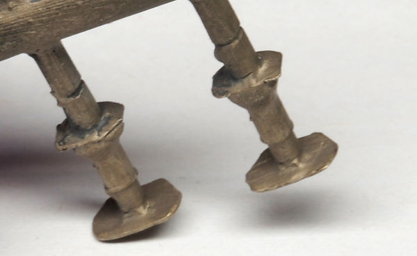
So I will only keep the bases, refining them, and I will remake the plates and plungers. The new plates are made of 0.3 mm thick nickel silver sheet metal, based on the model shown below:
Here is how I proceed:
- I mark the centre and trace a circle with a diameter of 6 mm using a dry point baluster on the nickel silver sheet metal;
- I cut around the circle roughly with Xuron shears;
- The ⌀ 1 nickel silver rod, approx. 10 mm long, is clamped in the chuck of the mini drill, which I lock in the lower position, and the plate is placed on a wooden support to ensure the best possible perpendicularity.
- Here are the parts waiting to be soldered (with flux applied, I should point out, as it is not really visible…) ;
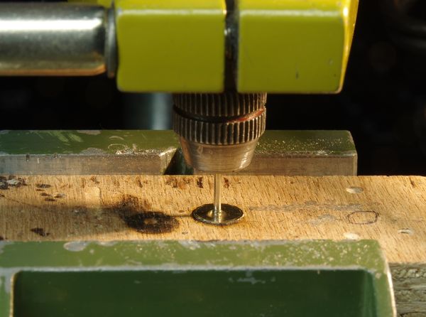
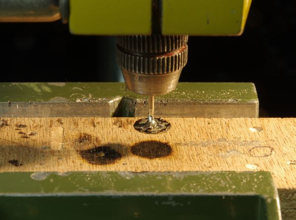
- Silver-tin solder in sufficient quantity to create a strong joint for machining. Soldering complete, drill raised:
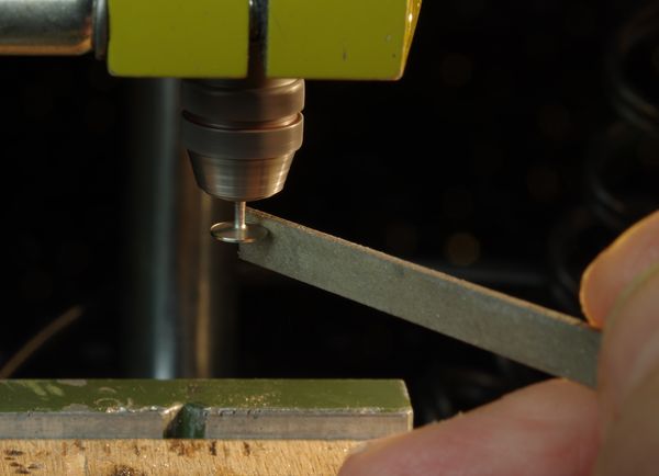
- Turning in the mini drill: roughing with a diamond disc then finishing with a soft file, to the required diameter of 5.8 mm;
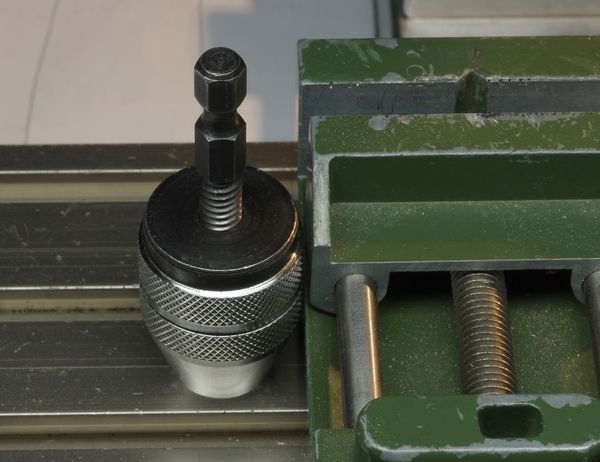
- Placing the buffer in a hexagonal shank chuck for a screwdriver;
the fact that the shank is hexagonal will make my job easier, as we will see.
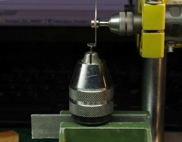
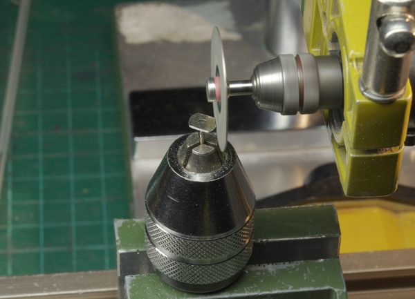
- Horizontal drill, equipped with a diamond disc, machining the first flat surface to 0.8 mm. Rotate the chuck 180° in the vice; machine the second flat surface to the same distance;
- Check that the width on the sides is correct (4.2 mm). I could stop here, because some plates, like the one in the Loco-Revue photo, are of this model. But I am going to complicate things a little more…
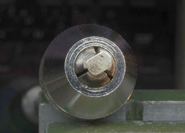
- Rotate the mandrel 120° (this is where the hexagonal shank comes in handy!); machine the first oblique secondary flat surface to 0.35 mm, then, after rotating again by 120°, machine the second flat surface;
- Sand the plate (deburring and rounding) with 400-grit sandpaper held in your finger;
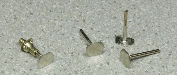
- Turn the rod and the back of the plate with a flat file to remove as much solder as possible; finish with a rat-tail file to obtain a small connection fillet.
Here are the four finished plates.
Now it is time for the bushings. I cut the rod flush with the bushing, then drill to a diameter of 1.1 mm.
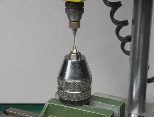
The corners (arrow) still need to be milled, again using the screwdriver chuck and a ⌀ 1 milling cutter. The bushing is positioned at an estimated angle of 45°. Sorry, I did not take a photo.
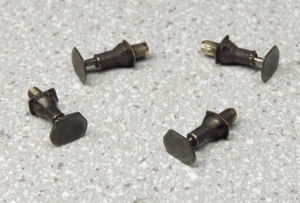
Here are the four finished and burnished buffers.
To solder the buffers onto the buffer beam, I use a template with a 20 mm centre distance, on which I place the bushings:
But, before soldering, I shorten the tails to about 1 mm, otherwise it will be impossible to mount the body on the chassis.
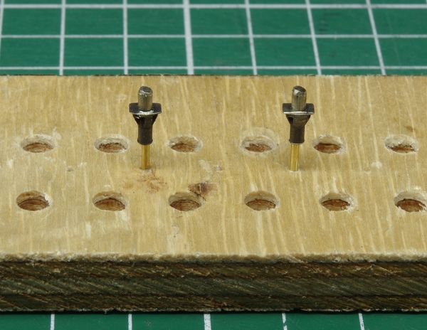
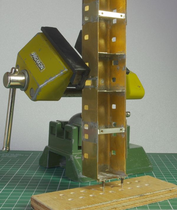
Once the bushings are aligned, I position the body perpendicular and hold it in place with the vice slightly tightened.
Close-up view.
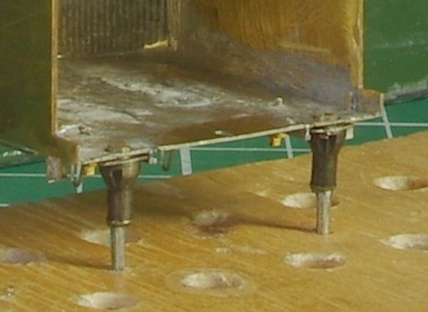
All that remains is to solder with tin-bismuth using plenty of flux so that the solder penetrates between the wall and the buffer base.
Result :
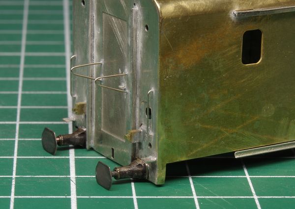
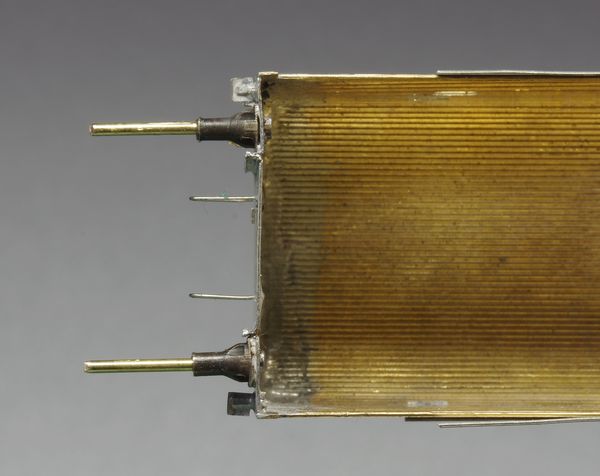
In the previous photo, you can see that the alignment is not perfect. I check it with gauges, vertically…
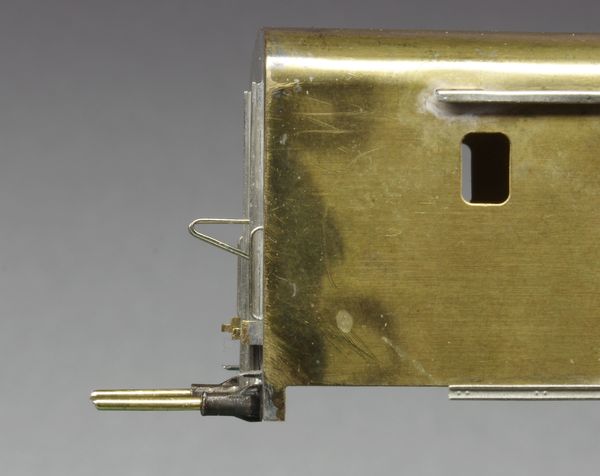
… and horizontally.
Bismuth solder, which melts very quickly, allows for easy position corrections, which I make on the same template. In addition, when melted, it becomes very shiny, whereas when cold, it is matt. This makes it very easy to see when to stop heating and, conversely, when to let go!
Taillights
I plan to install ⌀ 2 cylindrical LED in the large taillights. However, the ones supplied are made of transparent resin. This is annoying because, even when painted, there is a risk of light leaking through the surrounding area. I think it would be better to have a metal casing.
In terms of dimensions, the outer diameter of the large lights supplied is 3.1 mm, and that of the bases is 2.0 mm; they fit easily into the holes in the recesses. The small lights, with diameters of 2.0 and 1.2 mm respectively, require the holes to be slightly enlarged to ⌀ 1.3 (reamer).
I do not want to light the small lights, so there is no need for tubes for them. I will keep the parts provided.
For the large lights, I have ⌀ 3 brass tubing. I also have ⌀ 2.5 tubing that can be fitted by slightly reaming the 3 mm tube. This has two advantages: the ⌀ 2 LED fits perfectly into the ⌀ 2.5 tube, and the latter can be used for centring in the recess by reaming it to 2.5 mm.
Construction
- I cut pieces of ⌀ 3 and 2.5 tubes, approximately 10 to 15 mm long;
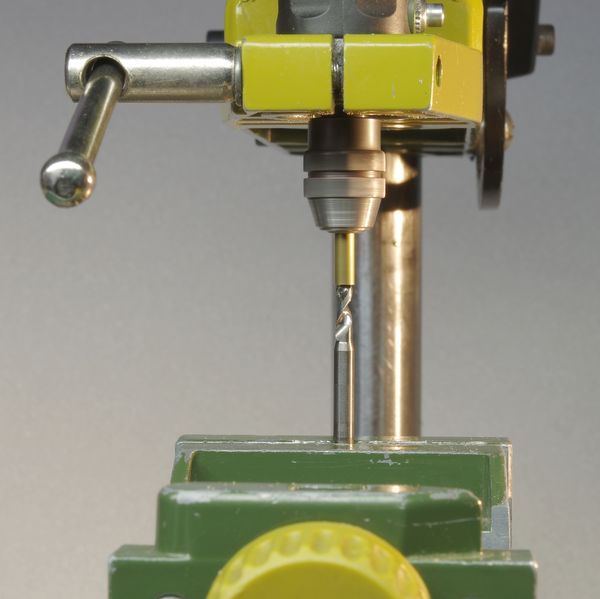
- I bore the ⌀ 3 tube (photo) to a diameter of 2.5 (tube on the drill, drill bit in the vice, as a slight misalignment is less of a problem this way);
- I cut the ⌀ 3 tube into 2.6 mm lengths (outer part of the lamp);
- I cut the ⌀ 2.5 tube into 4 mm lengths (actually, this is the length of the LED “barrel”);
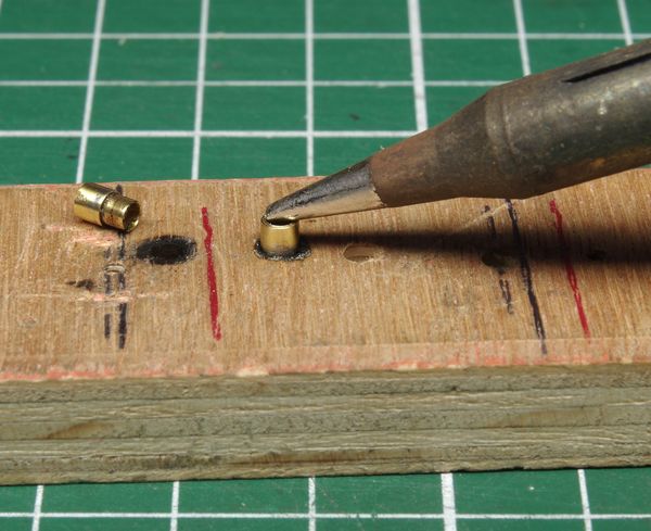
- I solder two sections together, with a common surface. To do this, I “planted” the ⌀ 2.5 tubes in a 2 mm deep hole drilled in a piece of wood. I coated them with soldering water, then slid the ⌀ 3 tubes over them. Heating with the addition of a very small amount of tin-silver solder;
- Clean with a file, paying particular attention to the visible surface, then finish with 1000-grit sandpaper.
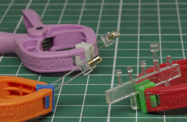
Appearance of parts mounted on canon LEDs compared to the original resin part.
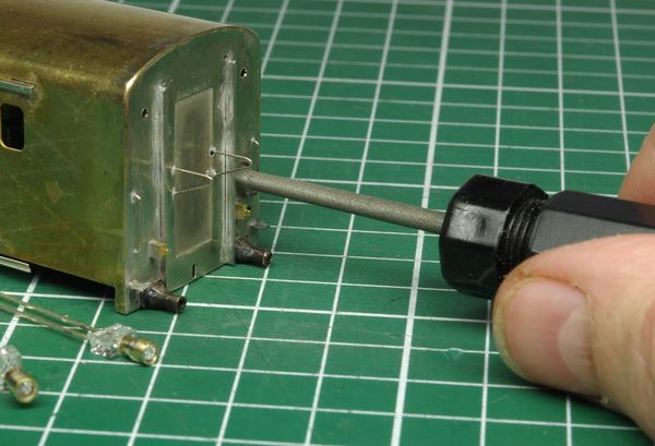
To allow for assembly, the holes in the end walls must be enlarged (from 2 to 2.5 mm). I use a rat-tail file, not a drill bit, which could damage the surface. The file also allows me to correct the position of one of the two holes, which was not properly centred.
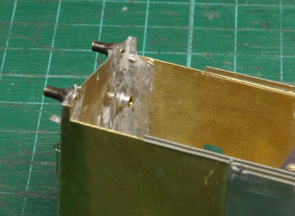
Soldering with tin-bismuth solder, from the inside.
Appearance of the solder joints, interior view…
… and exterior view.
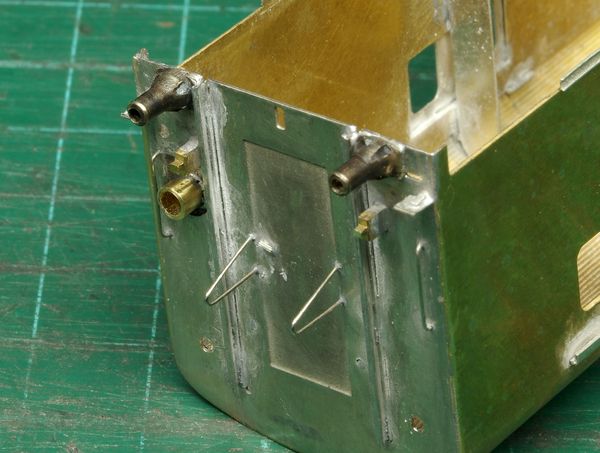
View with LED mounted:
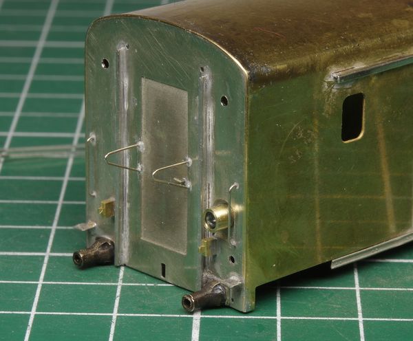
Body-chassis adjustments
Assembling the body and chassis poses a few issues, but nothing too complicated to fix.
In terms of length, the chassis fits perfectly into the body. That is a good thing! The same cannot be said for the width.
- At the ends, the lower wing of the side beams needs to be slightly notched, approximately 2 mm, depth 0.5 mm:
- On the sides, the chassis is a few tenths of a millimetre (barely) too wide to fit into the body. I had to mill the edges of the body. It is not very pretty to look at, but I do not want to hide anything.
However, there is a much simpler and easier solution, provided you think of it before assembly. This involves not soldering the partition walls 10 mm from the bottom. This way, by playing on the elasticity, it will be possible to slightly spread the edges of the body to fit the chassis inside.
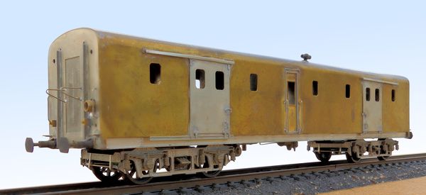
Progress photo
This photo shows the model before the three-point height adjustment described on page 1. Here, 1 mm washers are inserted between the bogies and the chassis, resulting in a height of 45.0 mm, compared to the actual 1:87 value of 44.7 mm. The buffers are at the correct height, but, as already mentioned, this is insufficient to allow for pivoting; it is 0.5 mm short.
To be continued…