Page created on 11/07/2025.
The body: a nightmare!
Assembly problem!
I temporarily position the interior partitions to see… and I see… that there is a problem.
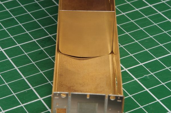
The same with the end walls.
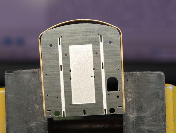
The body has apparently been bent incorrectly, and there is a significant gap between the walls and this body. I send an email to AMF87, who replies quickly: “If you follow the instructions in the manual, the body will take on its shape by itself.”
But I did read and follow the instructions in the manual carefully. And yet…
Soldering attempt
The instructions say: “Solder the ends, making sure they are perfectly centred. To solder correctly, apply a drop of solder to the centre of the assembly. If everything is correct, press the end into the corners of the body and apply another drop of solder.”
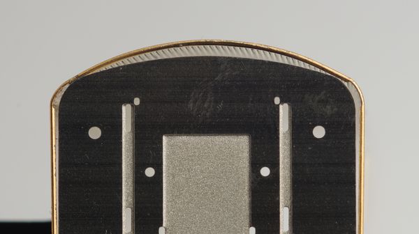
Alright. So I will put a dot of solder in the centre… but how, given the gap between the end wall and the roof? The radius of the arch is clearly smaller on the roof than on the end wall.
OK. Let’s not be defeatist. I will give it a try anyway. To do this, I need to increase the radius of curvature of the roof, flattening it in a way, which has the effect of spreading the side walls apart.
I position the parts “making sure they are perfectly centred” and apply a (large!) solder spot in the centre. The parts are held in place between pieces of scrap epoxy to limit heat loss. A heavy ruler ensures perpendicularity.
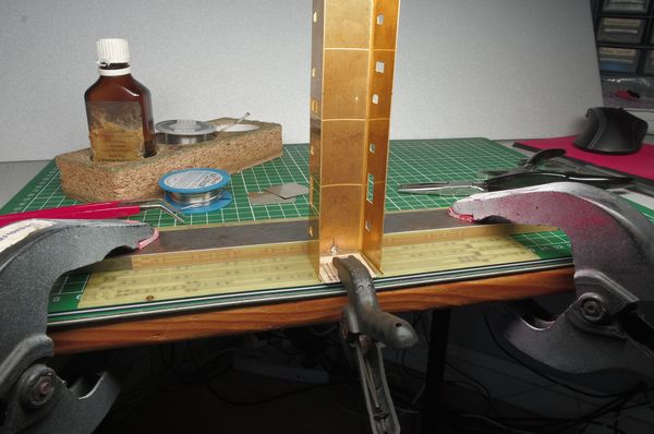
Click on the photo for a closer view.
Now, I “press the corners of the body” (according to the instructions, again):
Then, “the body will take on its shape by itself”. Hmm…
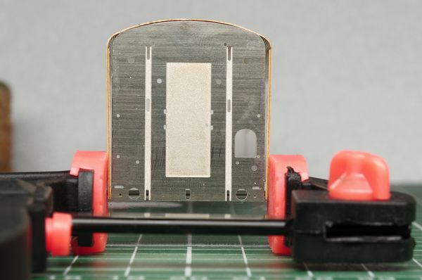
Click on the photo for a closer view of the curve.
Same observation as before: the main arch of the roof is too long — not just a little: at least 1 mm on each side — and the small side arches have both too small a radius of curvature and too short a length. Conclusion: correct bending… or not? How can I correct this without a bender?
I should point out that what made me decide to buy this kit was precisely because the body was already shaped, as I did not feel capable of doing it myself. Here, not only will I have to bend it, but I will also have to “unbend” it first. Uncomfortable…
By the way, what is the correct width, that of the end walls or that of the body? I have a pretty good idea of the answer, but I will check. The width of the body of the real van is 2 505 mm, or 28.8 mm at 1:87 scale; the width of the AMF87 end walls is 28.6 mm; that of the body is 31.2 mm. The answer is clear.
Conclusion: as it stands, I will not be able to shape the body on the walls by hand. Even with a (small) vice, I was unable to bring the edges together (without using excessive force, of course). I will leave this to the “pros” who are skilled in brass work AND bodybuilding, with nimble fingers and nevertheless super-muscular…
So, I need to find another way to correct the curvature of the roof. Let’s analyse the problem. The central arch is too long. The side arches have too small a radius and start too far away (at least 1 mm, as already mentioned). They therefore need to start closer to the symmetry axis.
I first redrew a partition wall in AutoCAD, scanned directly from the photo-etched parts. I “vectorised” it (by hand) and obtained this sketch.
In comparison, the side arches of the body have a radius of around 2.5 mm, which is insufficient, as we have already seen in the photos, and its main arch is 28 mm long, which is too much, and significantly more than I had estimated.
A template for (re-)shaping the body
I make a template based on a ⌀ 6 steel rod (a⌀ 7 might be better, given that the desired radius is 3.7, but I do not have one).
This steel rod is held in a rebate cut into a batten so that it is flush with the side wall and protrudes 2 mm upwards. The opposite corner of the batten is cut away to allow the body to move.
A second batten sandwiches the body wall.
The body is clamped between the two battens with wood screws. It is ready to undergo the boot torture.
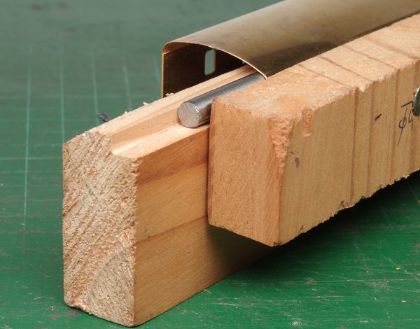
Here is the torture itself. I have to use all my weight to get an effect. So, do you really think that simple finger pressure would have been sufficient?
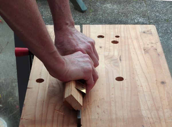
Result on the first side.
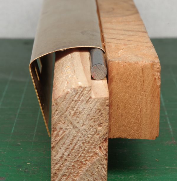
Comparison: the right side is treated, the left side is not. Left image: the partition wall is placed on the left side (untreated) of the body, held in place with Blu-Tack. Right image: same thing on the right side (treated).
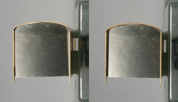
Zoom.
We can see that the curve on the right starts closer to the symmetry axis. There appears to be a slight crease under the tip of the arrow, but this is an optical illusion.
The half-engraving intended to promote the curvature of the small arcs is clearly incorrect: it should have started closer to the axis.
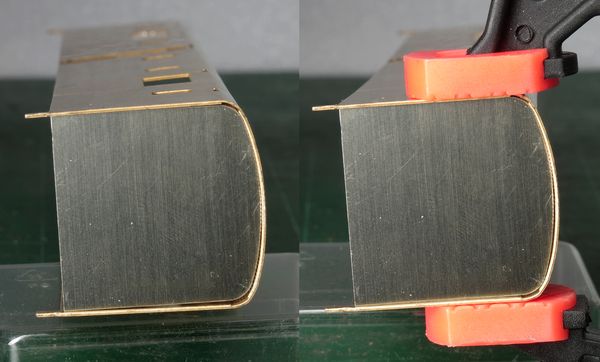
Finally, here is the condition of the body after the second side has been treated. On the left, without stress. We can compare this to the photos from previous episodes: it is not perfect, but there is much less gaping.
On the right, under slight stress, we can see that it will now be much easier to achieve a satisfactory result.
Assembling the body (new attempt)
Before soldering, I tin all the parts, including the body, with soldering water.
End walls
So I start again by putting a solder drop at the centre of an end wall, then on each side of the roof, as recommended. Next, I clamp the whole thing moderately in a vice, protected by wooden plates, and finish off with a “bead of solder”.
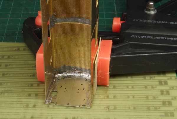
Exterior view. A little tin has spilled, due to my generous application of flux. Cleaning, and perhaps re-drilling some holes, will be necessary before soldering the details on the end walls.
The second end is soldered in the same way.
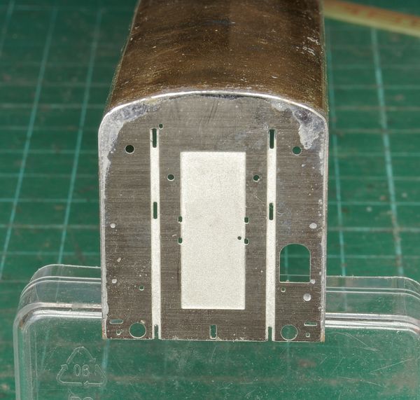
Partitions with fixing nuts
I find the location of these partitions, which cut the doors in half, highly questionable. In fact, they should be in line with the bogie pivots. I understand that this choice is more practical for fixing the body to the chassis, but it would have been better to use low crossbars and proper partitions in the correct location.
Same process: three solder spots under the roof, pressing it down as best as possible, then a clamp to press down the sides, and a solder bead.
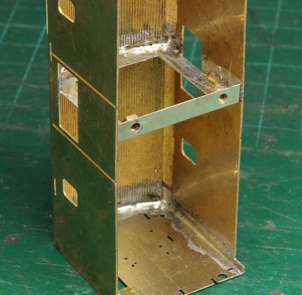
Note: I applied the solder on the nut side; I should have done it on the other side, because the bent tab prevents the iron from reaching the bottom. But it is not a big deal that a bit of tin misses in that spot, and I can always add more on the other side if necessary.
Before soldering the sides, I check the perpendicularity and position the frame to see if the mounting holes — fortunately designed to be oblong — line up with the nuts.
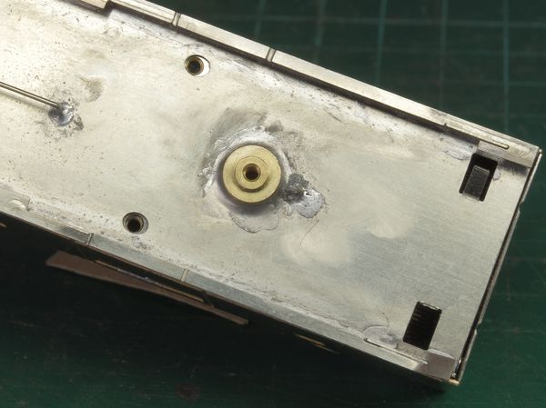
For information, the fixing centre distance in length is 101.5 mm. This is useful to know when checking the positioning of the second partition.