Page created on 11/07/2025.
Detailing the body ends
Lantern niches
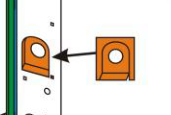
Here is the drawing taken from the instructions. It looks as though the niche is recessed and that there are side walls. But no, the part is simply attached behind the wall. It is positioned using the small tabs at the bottom, which must remain behind the back panel, and the folded part, which rests on the cut-out in the back panel.
The lower part must be folded, but not the tabs on either side. I assume that the engraved line on the tabs is only a guide for folding. On the left, the part already folded; on the right, the unfolded part seen from the back.
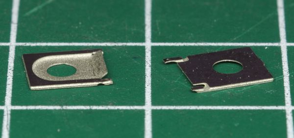
The instructions give a folding angle of 45°, but I think 30° (approximately) is preferable. If I fold at 45°, the part slightly shifts downwards.
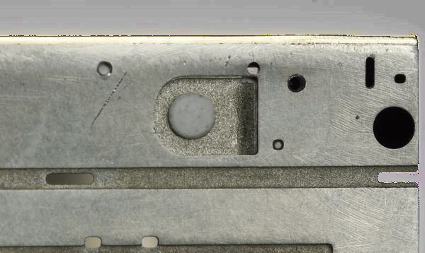
This is the result of folding at 30°. Temporarily held in place with Blu-Tack.
End wall reinforcements
These parts are very thin and will be difficult to solder.
I regret that the tenons are too short — 0.3 mm — and cannot penetrate the wall, even though notches are provided in it, which makes it more difficult to position and solder. In light green: extension of the tenon that would allow it to be inserted into the wall.
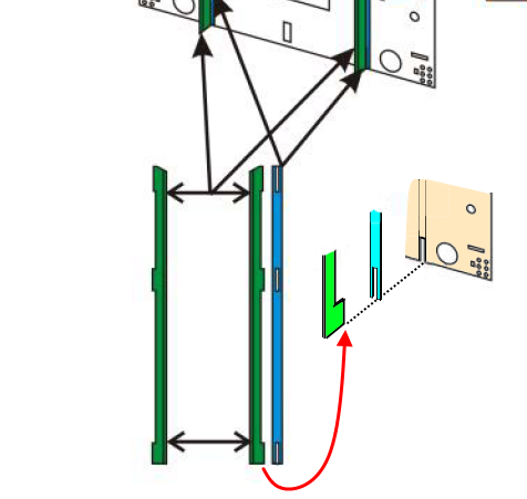
Assembly: the green parts are first tinned and soldered back to back, the hardest part being to superimpose them exactly. To prevent them from rotating relative to each other, I block them against an epoxy wedge.
Once soldered, I place them in a vice, file them and add a layer of tin (soldering water).
The blue part is even more delicate. I secure the green parts between two 0.8 mm thick epoxy wedges (the parts are 0.9 mm high excluding the tenon). The wedges must have a perfectly perpendicular edge, otherwise the parts will become misaligned.
- Epoxy baseplate.
- The two epoxy plates enclose the green parts.
The blue part is soldered with small slices of tin-lead (circle) where there is a notch (arrows). It is held in place by another epoxy plate.
Here are the four finished uprights.
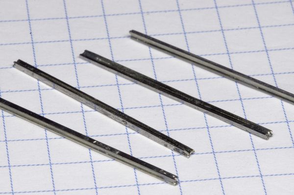
Does their shape ring a bell? What if I show you this:
For those who do not feel capable of assembling such small parts, here is another option: simply reduce the size of the rail bottom!
Note: the half-engravings on the end wall designed to hold these uprights are 1 mm wide.
Code 55 rails are available from micro-modele, for example.
Soldering the end wall reinforcements
This is how I hold the uprights for soldering. Exterior view, for soldering the points at the top of the body:
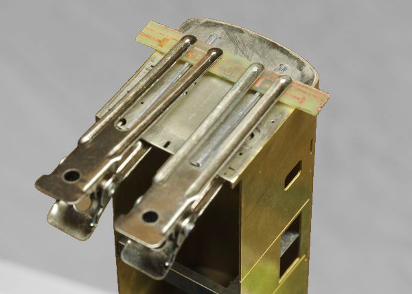
Interior view. The upper points are already soldered (circles). I lowered the clamps for the lower points (arrows).
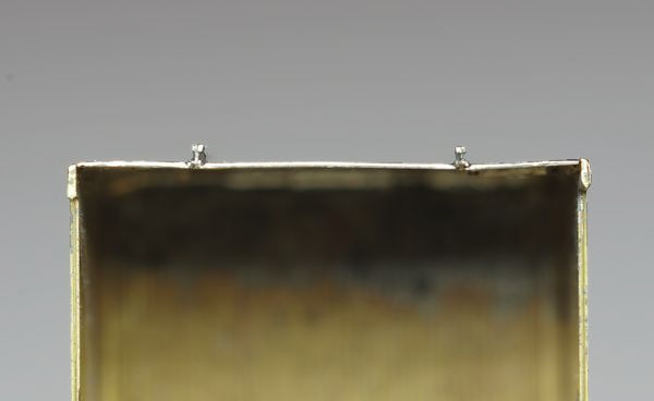
View from below of the soldered uprights. You can see how small the parts are. The perpendicularity is not perfect, but it is better than I feared at first. The end plate is slightly deformed.
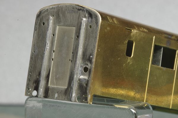
Here is a three-quarter view. Of course, there is some cleaning to be done! The bottom of the lantern has also been soldered.
Railings
For anything cylindrical, I prefer, as far as possible and reasonable, to use cylindrical parts rather than photo-etched and therefore flat ones. Of course, from a distance, photo-etched parts look realistic, but, for the same width, they are much more fragile than round ones. Obviously, this takes a little time, sometimes requires modifying the fixing holes, and requires the parts to be spaced at the correct distance for soldering.
These railings, made of ⌀ 0.3 nickel silver wire, are made using a template (brass or nickel silver rods drawn as broken lines in the following drawing).
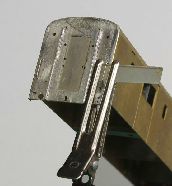
Soldering the end handrails
When soldering the handrails, they must be held at the correct distance; to do this, I slide a small 0.8 mm epoxy card underneath them. In the photo, for clarity, there is only this card. In reality, there is a second one on top, because I am going to solder from the inside: the part must be prevented from falling.
The soldering is done with a small slice of tin, say 0.5 mm thick for a 1 mm diameter solder wire.
Soldering the gangway handles
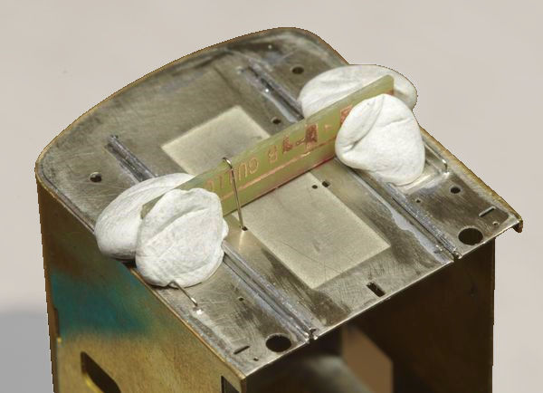
The spacing can also be adjusted using an epoxy plate, but placed perpendicularly and held in place with Blu-Tack. This plate must be 5.9 mm wide minus the protrusion of the uprights (1.2 mm), i.e. 4.7 mm.
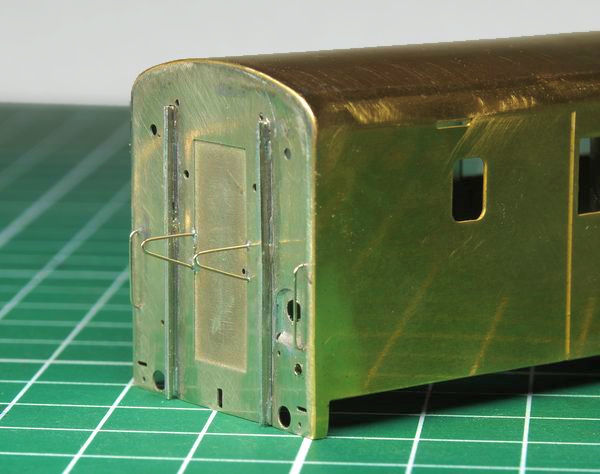
Result.
Lamp holders
Here is the part provided in the kit to represent the lamp holders. It is very small and may be suitable for the old system with male supports, but not for the more recent system with female supports, which can be seen in photos from the 1970s.
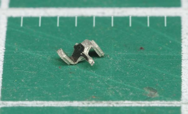
Note: the graduations are in millimetres.
Here is the plan for the new lamp holders that I intend to make.
These lamp holders are cut from 1 mm brass sheet metal. They are drilled at the back to accommodate a nickel silver fixing tail. The front part will be shortened according to the plan.
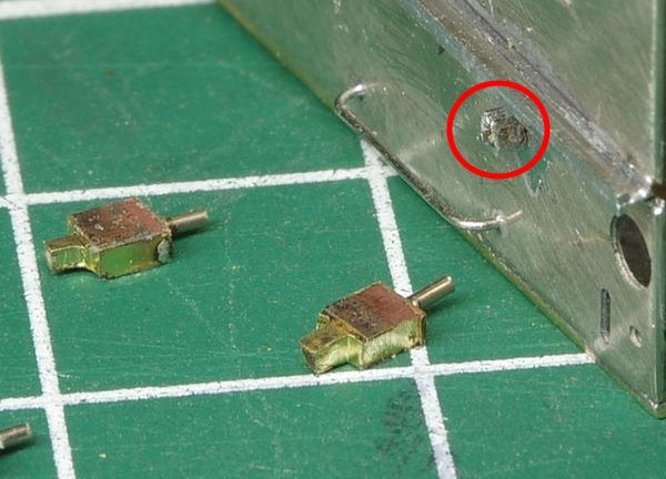
The position of the fixing location is circled in red.
Test assembly with the bellows (too low), heating jumper and buffers temporarily in place to check the size. It looks correct.
So, the four lamp holders are soldered.
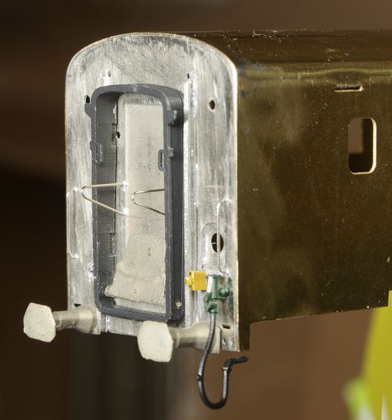
Note: I have accentuated the colour of the lamp holder to make it more visible.
Bellows
The kit comes with one unfolded and one folded bellows; I would have preferred two folded bellows. Since this van does not have a corridor, I do not think there was often a need to connect the gangways.
On the other hand, I have a number of bellows from LS Models Rapide Nord coaches, which are much finer, with “3D” hangers rather than flat photo-etched ones. So I will use those.
The question of how to attach them arises. It seems difficult to mill mounting holes for these bellows now that the end walls are soldered. So I think I will trim the tenons (dotted lines) and glue them with CA glue.
As for the gangway plates, I do not have any LSM models in stock, so I will have to salvage the ones moulded with the AMF87 bellows (arrow on previous photo) by sawing them off. I will glue them in the folded position on the interconnecting doors.
A suggestion to the kit manufacturer: make them in photo-etched form and supply bellows without gangway.
As for the suspensions, those from LSM have 0.5 × 0.9 tenons. However, the holes in the wall, designed for thinner pieces, are very small. I cut the tenons of the suspensions to a height of approximately 0.5 so that they can be inserted into the holes in the walls, which have been enlarged to ⌀ 0.7, using a hand reamer (because enlarging a rectangular hole with a carbide drill bit, freehand at that, is almost certain to break the drill bit).
On the left, the intact part; on the right, the modified one.
Small end steps
The small corner steps are not at the correct height:
Note how the angle of the photo is almost identical to that of the real model… Also note that, although the chassis has been raised on its bogies as planned, this does not appear particularly striking. See, for example, the distance between the primary suspension springs and the bottom of the chassis.
We can see that the proportion between the height of the step and that of the chassis is reversed.
After examining photos and diagrams (unfortunately, I do not have a detailed plan), I can see that the running board is clearly too low and offset towards the centre (it should be flush with the corner of the body, which will make it easier to pass the electric heating jumper). The visual offset is all the more noticeable because the chassis is, on the contrary, slightly too high.
It is only a detail, but it will force me to drill a new fixing hole, provide a round support (because the hole is round!), and fill in the current slot.
So, a word of advice to future assemblers: do all this before assembling the body, quietly, on a flat surface.
After marking the new position with a dry point baluster as a marking gauge, I drill with a ⌀ 0.5 drill bit.
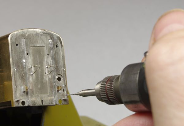
I remake the supports in ⌀ 0.5 nickel silver, flattened with flat pliers under the step. Soldering with tin-silver.
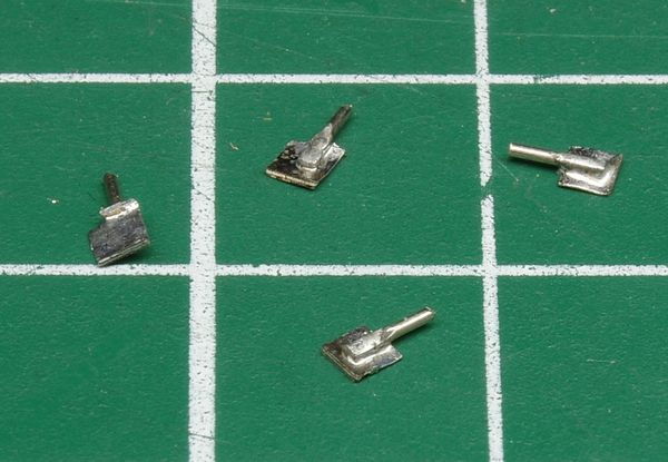
Soldering the assembly in place with low-temperature tin-lead-bismuth solder. Check: the electric jumper will pass smoothly alongside the step.
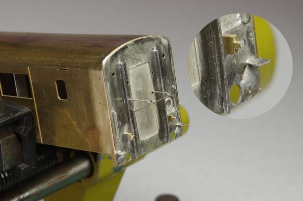
I fill the original slots with tin-lead-bismuth solder. I put a little too much on, so I will have to do some scraping. Let us hope it does not come loose when the buffers are installed. I do the same for the bellows mounting holes, from the rear. The solder fills the holes well, without overflowing onto the outside.
I finish by soldering the tiny door handles.
Peco code 55 N track
Length 914 mm
Reference SL-300F
€6,70 at micro-modele