Page created on 19/07/2025.
Other body fittings
Chanard ventilator
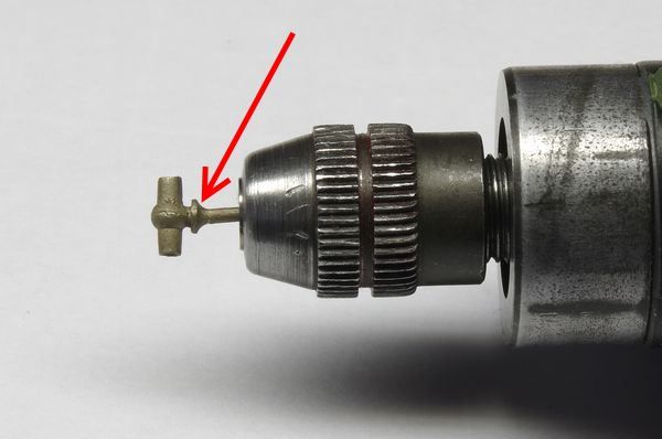
The ventilator has a fillet (arrow) on its base that prevents it from sitting properly on the roof.
The ventilator is corrected by filing after aligning the axis, which was really crooked!
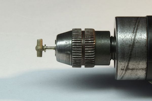
After lightly filing the air inlets, I hollow them out to a depth of about 2 mm. The plywood support is drilled with a ⌀ 1.6 hole. The aerator, being slightly conical, fits snugly into this hole. Non-through ⌀ 1 drilling.
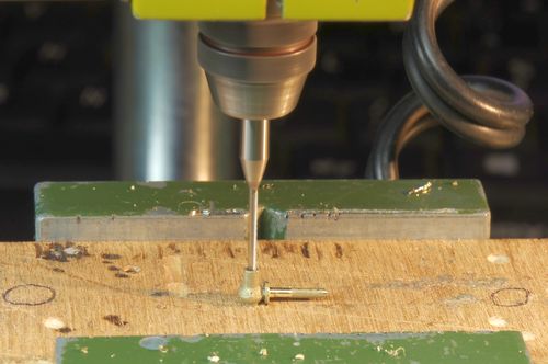
Click on the photo for a close-up view.
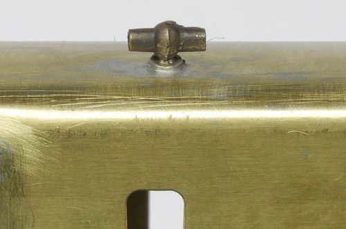
I finish with a burnishing. Soldering with tin-lead-bismuth + flux, which is quite difficult because the parts are relatively massive and, in addition, the ventilator must be kept aligned on two axes. I did not succeed on the first try…
The solder joint obtained is correct and discreet.
Compartment doors
Installation of door frames and gutters
Installation by tinning with soldering cream on the body and parts; ironing after flux coating. However, the frame inside the door engraving is not properly centred.
Door handles
As for the door handles, the holes have been forgotten! They should be located about 1 mm below the window frame, on the left in almost all the photos. But they are sometimes on the right. Are there special vans for left-handed train drivers?
⌀ 0.3 drillings.
The handles are made of ⌀ 0.3 nickel silver wire flattened with flat pliers to represent the handle itself, soldered with a 2/10 thick sheet of paper in between.
Manufacturing and shaping the handrails
Here, as with the other railings, I do not want to use flat photo-etched parts, but round ones. Here is the plan I am going to try to carry out, following the real railings as closely as possible, which I find the designers were a little… tortuous!
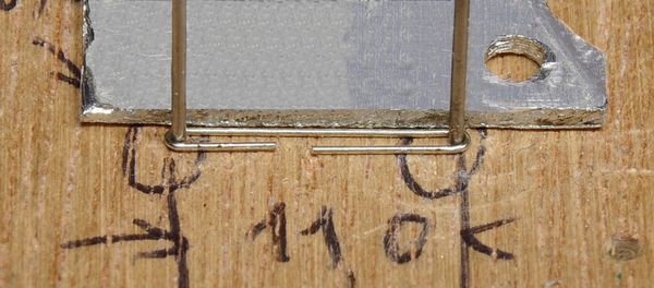
The bending is done in three steps, the first two on a template made up of two ⌀ 0.6 drill bits spaced 11 mm apart:
- Folding the ends back 180°; the piece is held against the drill bits by any kind of plate, in this case aluminium.
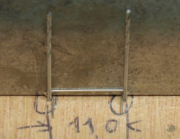
- With the piece now clamped vertically, fold again by 90°, the most difficult part being to balance the overhangs on each side.
- In the vice, holding the ends with a flat screwdriver, rotate a third time by 90°.
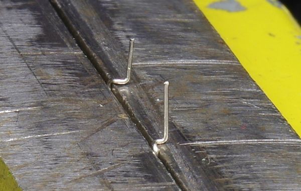
Finished parts: the result, although not perfect, is better than expected.
All that remains is to drill the holes that are only half-engraved (I do not know if this was intentional). I drill at ⌀ 0.3, since my handrails have this diameter. If necessary, I enlarge the holes a little with a hand reamer.
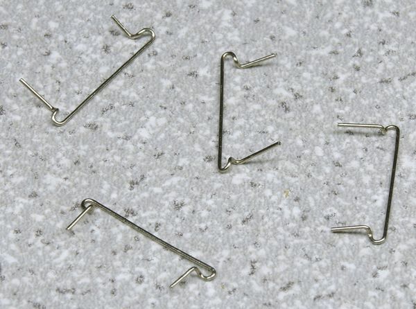
For assembly, just make sure everything is perpendicular. There is no need to insert a spacer, as the parts themselves act as stops.
Result.
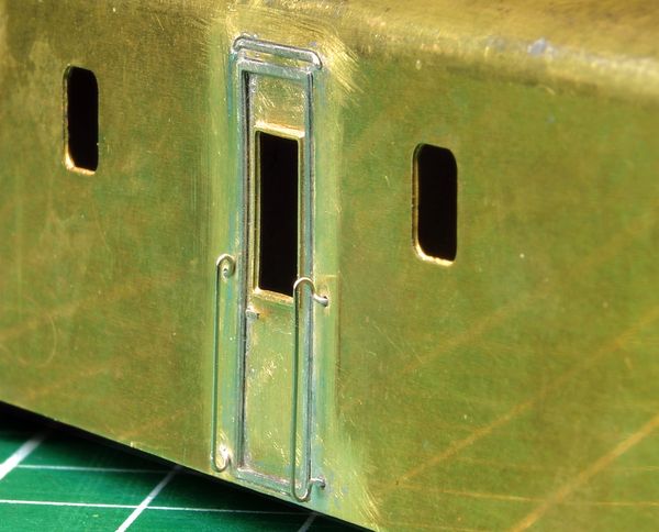
The photo shows that the frame is not properly soldered at the top. However, the handrails look satisfactory, even in close-up.
Sliding doors
Door fittings
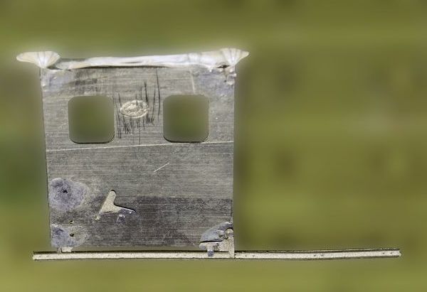
To install the fittings, I tin the corners of the doors and their fittings themselves before removing them from the photo-etched plate. Given their small size, this makes it easier. The most difficult part is holding these parts in place during soldering. The door is taped to the epoxy support plate. The tape is placed far enough away from the heated area to prevent it from melting and contaminating the metal.
After applying flux, position with the tip of a scalpel and hold with a wooden stick. There is no need to apply flux to two areas at the same time, as the first soldering will evaporate the flux from the second point. No additional tin is required.
Slides
Given the narrowness of the slide wings, folding is very difficult, despite the half-engraving, because the lever arm is very short. To make folding easier, the fold line must be deeply grooved with a scalpel. Tip provided by a member of the Loco-Revue forum, whom I thank.
The part has its half-engraving positioned flush with the jaws of the vice.
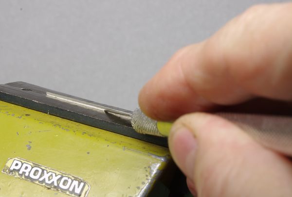
Click on the photo for a closer view.
Assembling the doors
After soldering a door with the risk of solder overflow (ellipses), I thought of drilling holes in the body behind the doors (circles) to bring the solder from the back.
The soldering will take place at the circled locations. Here, it is even more important than usual to position the part to be soldered correctly and hold it in place. I use spring-loaded clamps for this.
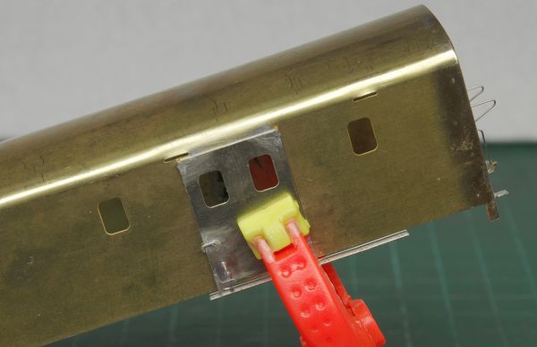
The best way to find the correct position is to refer to the false lower slide rail in relation to the bottom of the body.
To ensure that the part does not move during soldering, I start with a single solder point, which is easy to modify, then check the position again.
Here, for example, we can see that the parallelism is not perfect: there is a slight gap at the bottom right of the door, and the false slide is not perfectly parallel to the bottom of the body. This needs to be corrected.
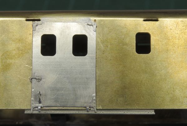
Next, the soldering is done in the order indicated (after removing the clamp, of course). At ① and ②, care must be taken not to overload with tin, as the door window panes will need to be placed there. In any case, the “chip” technique is required; here, 1 mm pieces of ⌀ 1 mm tin-lead wire were sufficient for each soldering point.
Mounting the slides
Already difficult to bend, the slides are also tricky to assemble. To make them easier to insert, the width of the tenons needs to be reduced slightly, and the mortises in the body, which have slightly narrowed during bending, need to be widened. As I do not have a file thin enough, I force an X-Acto blade into the slots, which slightly deforms the brass.
Next, these slides tend to “nose dive”. Here too, it is necessary to solder only one end at a time, checking and correcting the position each time. The more or less correct positioning is very visible due to the length of the parts. Here is the least bad result I have achieved.
The slots will need to be filled (with tin, putty?).
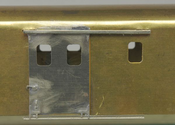
Problem
I then realise there is a problem: as the fittings are installed as indicated in the instructions, i.e. at the top corners, they cause the door, when it hits the top slide, to be too low. This can be seen on the bottom slide in relation to the frame. (Drawing taken from the instructions).
- Actual position.
- Expected position.
I thought I could solve this by cutting off the small protrusions on the upper fittings, but not only did the windows remain offset downwards (by 0.8 mm, measured directly on the van), but this also created another problem: the fittings were half hidden by the slide.
To fully understand the problem, I needed a diagram with fairly precise and detailed dimensions, which I do not have. So I made one based on an actual profile photo, taking parallax into account as much as possible. In the image below, the diagram can be superimposed on either the actual photo or the photo of the AMF87 model under construction.
You can use your browser’s zoom function to see more details.
What can we see?
- The diagram overlaps well with the photo of the actual van. This is normal, since I built it from this photo. The coincidence is a little less good on the right half, because I drew it symmetrically from the left half. Apparently, the actual van is not perfectly symmetrical, or, more likely, there is a slight distortion in the photo. The dimensions shown are taken from the diagram, with a scale factor of course; they correspond to the actual dimensions.
- On the other hand, the overlay is less accurate with the model, which is hardly surprising. But it should be noted that the slides are clearly too low, and that there is a slight upward shift in the body windows compared to reality, and, conversely, a downward shift in the door windows, hence the difference in level observed.
- The compartment door is also clearly too low and shifted to the left.
For this last point, there is nothing we can do, as the door is engraved directly into the body. As for the van doors, in order to align the door windows with the others, the doors need to be raised by 0.8 mm. The problem is that they are already at their upper limit on their slides. Shorten them? Impossible, because their fittings are fixed in place! Raise the slides? In my opinion, this is the best solution, but it will be necessary to unsolder everything without touching the rest. And take the opportunity to increase the thickness of the doors, which has also been criticised on the forum. As this is a risky operation, it will have to wait for better days (note: this observation dates from January 2019)!
Let us not get discouraged and continue with the assembly.