Page created on 11/07/2025.
I need at least one metallic Est-type bogie luggage van for various compositions. My good old HOrnby acHO van is really outdated, and the model announced by R37 is still pending.
So I started (January 2019) building the AMF87 van, reference K129. A similar topic already exists on the Loco-Revue forum, concerning the AMF87 Sud-Est metallized van. However, its construction process has not been fully described. It is the purpose of this article.
I had actually started this description in the same forum, but I stopped for a reason that will be explained on page 4.
Presentation of the kit
Contents of the package
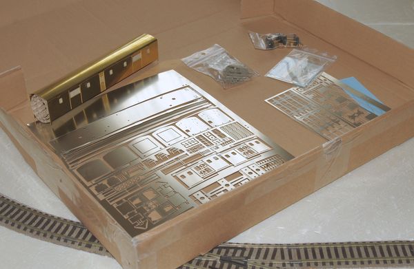
Composition
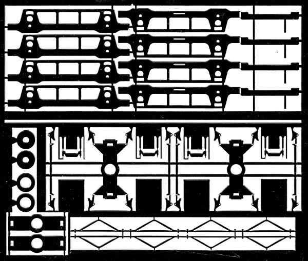
Here are low-resolution scans of the various elements, photo-engraved nickel silver plates and others.

The decals are available in SNCF and UIC markings.
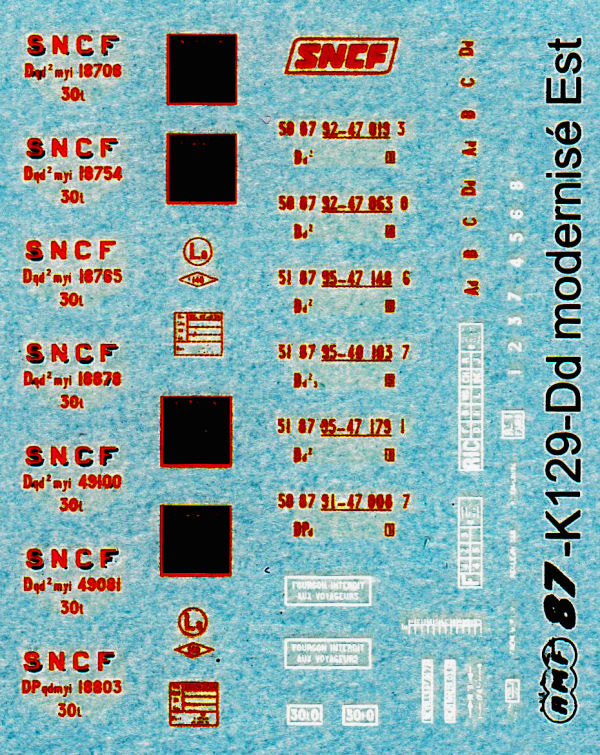
Note: I have maximised the contrast of the image to make it easier to select the text, especially the white text, which is practically unreadable on the original sheet. Unfortunately, this is the case for all the decals.
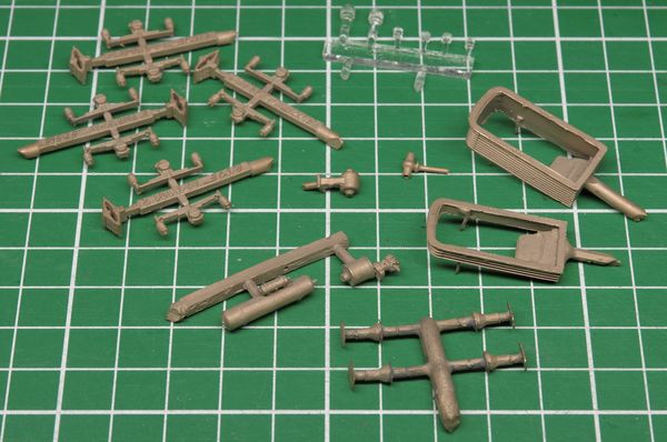
Nickel silver castings: suspensions, brake equipment, toilet ventilator, buffers, bellows; transparent resin for the headlights.
There is also the preformed body, made of 0.5 mm brass, a bag containing the axles with very fine spokes, and, of course, instructions.
Assembling the bogies
Note: assembling the bogies takes quite a long time, and the result is rather mediocre, given the lack of finesse of the cast parts compared to those made of injection-moulded plastic. It may be worth looking for WL bogies from Est coaches known as “Romilly” by De Massini or EPM (Roco also makes them for their Bruhat, but they are of a different type and not compliant), or Y2 bogies originally made by REE or Jouef (OCEM), for example, for a 1970s version.
To begin with, here is a photo of a real WL bogie (SNCF photo).

Brake equipment
I want to replace the photo-etched brake block connecting bars with round bars. I start by enlarging the holes in the brake blocks to a diameter of 0.5 mm with a hand reamer.
I cut the flat bars directly on the photo-etched plate, about 1 mm from the corners, and solder a ⌀ 0.5 nickel silver rod 20 mm long onto them.
- Intact part.
- Part with the central part cut out.
- Part with round bar soldered on.
In addition, I double the thickness of the brake blocks with parts available not on the bogie plate, but on the body detail plate.
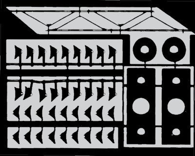
Due to this excess thickness, I have to cut the parts outside the “T-pieces”, otherwise the blocks would be too far apart.
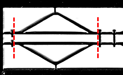
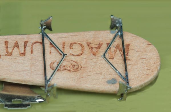
Installing the triangles: with the main part of the chassis lying on its back, I place a spacer with a total thickness of 2.8 mm on top of it. I slide the bar into the brake blocks holes; the triangle rests on the spacer, perfectly horizontal. All that remains is to solder very lightly at the blocks with soldering water, taking care not to unsolder the triangles.
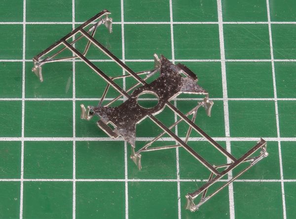
This is what the chassis looks like with its braking equipment, before the side beams are installed.
Side beams
Soldering the bearings into the side beam holes
This does not pose any particular problems.
Assembling the side beam decorations
The side beams are made up of two superimposed parts, a structure and a decoration. I tin each contact surface (soldering water), then position the parts on a piece of epoxy in which I have drilled two ⌀ 1.5 holes, 28.8 mm apart (bearing centre distance), into which the tails of the previously mounted bearings are positioned. The two parts are thus perfectly superimposed and held together.
The soldering is done from the inside so as not to damage the decoration (rivets), without adding tin, but with flux. Sometimes the bearings come unsoldered. They must be checked and put back in position if necessary.
Mounting the side beams on the chassis
To mount the side beams on the chassis, I made a simple template out of plywood, with an exact width of 21.6 mm between side beams and a length of approximately 40 mm. This allows each part to be held in place and its position adjusted.
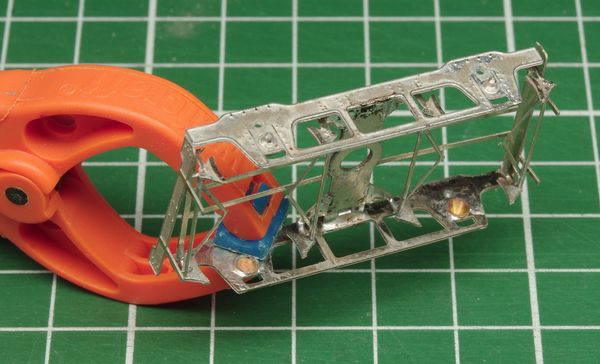
Tin-silver soldering with flux. Be careful not to block the rectangular holes that will receive the secondary suspension leaf springs.
Result.
Suspension
Mounting the leaf springs
These leaf springs are cast parts. After sawing, the fixing pins need to be filed down, as do the mortises in the chassis that have been filled in by soldering.
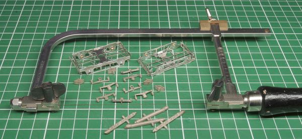
To mount the springs, the bogie is placed back on the previous template, but upside down. The two springs are thus trapped between the template and the chassis, making them much easier to position.
Another view.
Soldering with tin-lead solder and flux.
Assembling the axle boxes
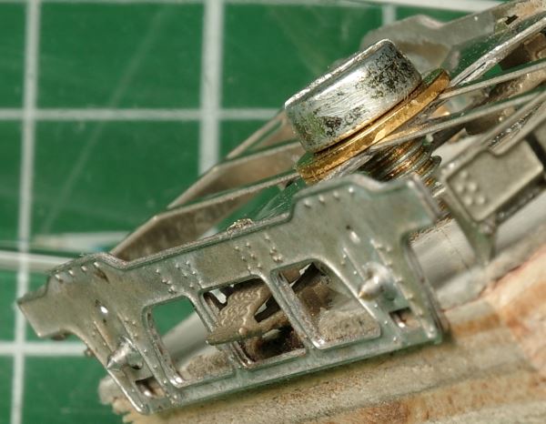
No particular problems. A few moulding imperfections need to be filed down, as well as the positioning pins, to facilitate soldering. Please note: sometimes the holes in the boxes are not deep enough, which prevents them from being pressed onto the side beams. In this case, the tail of the bearings, which is unnecessary anyway, needs to be filed down.
Soldering at the positioning pin, holding the parts in place with spring clamps. Despite this pin, the box can become slightly misaligned. So, check this each time.
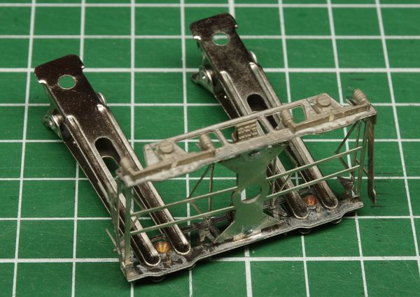
Note: by using too much flux, I soldered a clamp! Fortunately, it was easily unsoldered… To avoid this, wrap each arm of the clamp in a little aluminium foil.
Assembling the “suspension rods”
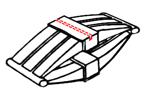
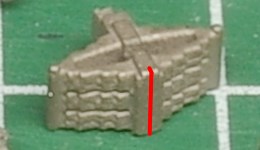
These parts are difficult to hold in place. I recommend — something I should have done myself — cutting a groove into the spring “bed” with a saw to guide this part, as shown here:
Soldering the cross-beams
Until now, following the instructions, I have not soldered the end crossbars to the side beams, in order to allow the axles to be fitted. But then the crossbars gape! Solution: solder the crossbars, not at the angle with the side beam, but at the ends of the chassis, near the brake blocks.
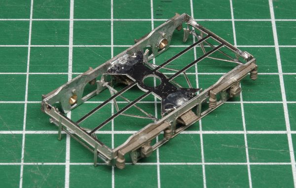
Click on the photo for a close-up view of the solders.
Assembling the chassis
The instructions say, “Bend the coupling support legs at a 90° angle, with the fold line on the inside of the bend.” I do not agree with doing this first, as these brackets are very exposed and may be damaged during soldering or cleaning the chassis. So, do this last instead. This is not a problem.
Personally, I broke one (red arrow), and its neighbour is not in great condition (yellow arrow).
Soldering the different parts
Decorations on the web sections of the side beams
No particular problems; you just need to make sure the parts are correctly aligned. Tin both parts, hold them in place with spring clamps, then solder with flux, but without adding tin, working from the centre towards the ends.
Web (vertical parts) of the side beams
To solder the webs to the chassis, start with a spot solder towards the middle to check the perpendicularity before soldering the rest.
Caution: the “decorations” tend to unsolder towards the ends.
Wings (horizontal parts)
For the wings, I placed a wedge as shown in this photo.
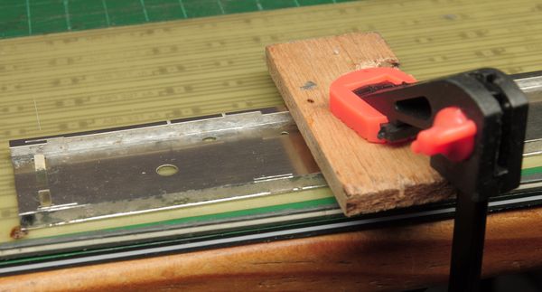
Finally, after soldering the pivots, clean with fibreglass and a steel brush.
Accessories
The accessories under the chassis still need to be fitted: cylinder, levers, hoop and brake reservoir, dynamo, battery box. The levers are held in place for soldering by a cardboard wedge of suitable thickness. I leave this wedge in place for as long as possible to avoid any damage.
A few criticisms:
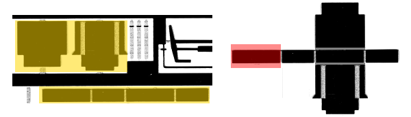
- The battery box is poorly designed, in three pieces, which are very difficult to fit together. It would have been better to make it in one piece, like a box. It would have been easy, especially since the upper part, which is invisible, was not essential (highlighted in red). On the left, highlighted in yellow, are the parts as they are; on the right is my suggestion.
- The parts: toilet drain, air tank and brake cylinder have ⌀ 2 mounting tails, while the corresponding holes are ⌀ 1.5. The chassis therefore needs to be re-drilled. Finally, the holes are better too small than too large!
- The dynamo prevents the bogie from rotating. It will need to be fixed further away.
A little touch of style: I used a ⌀ 2 brass tube for the toilet drain instead of the “rivet” provided.
To imitate the brake control bars, I soldered two ⌀ 0.6 nickel silver rods to the brake levers. They are bent at 90° near the bogie and soldered directly under the floor.

Assembling the side steps
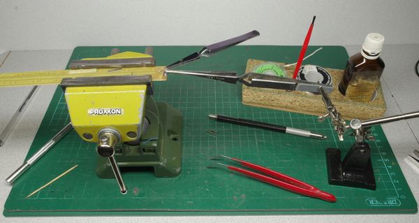
Here is an overview of the installation. On the left, the vice holds an epoxy board that serves as a support. The step to be soldered is held on top with a small clamp; the upright is held by tweezers, which are themselves held in a “third hand” that is used to position it at the desired level.
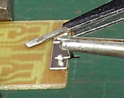
Once everything is in place, I add a little flux and a small slice of tin (lead). All that remains is to solder. I press the two pieces together with a very small flat-bladed screwdriver until the solder cools.
After rinsing to prevent the tools from becoming contaminated with flux (risk of rust), I insert a sufficiently thick piece of wood between the steps (3 mm for the side steps) to prevent the assemblies from warping. I scrape first with a file or scalpel, then with fibreglass.
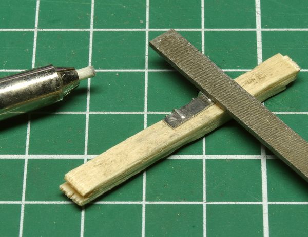
Here are the ten finished steps.
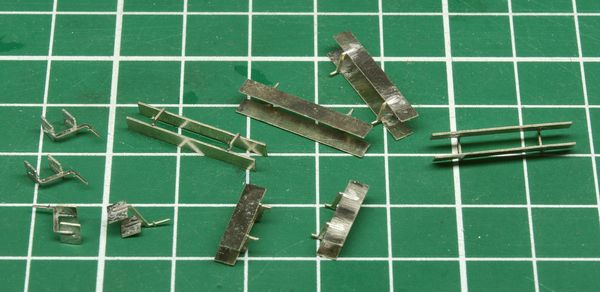
Due to the high risk of damage during subsequent handling, they will only be installed at the very end, before painting and decoration, contrary to what the instructions say.
Assembling the chassis and the bogies
The bogies mounted directly on the pivots (with Pozidriv screws for ease of installation, replacing the slotted brass screws supplied) cannot pivot because they are trapped between the chassis side beams. The height of the floor above the rail is then 13.6 mm. Its actual height, found in the Loco-Revue documentary sheet, is 1280 mm, or 14.7 mm at 1:87 scale. Raising it by 1 mm, which would be ideal, still does not work: a minimum of 1.4 mm is required.
For the time being, I am content with a stack of two ⌀ 4 large washers, 0.7 mm thick, which will be soon replaced.
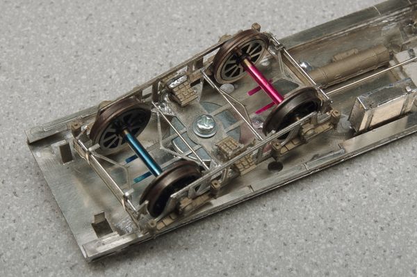
Some may wonder why the axle pins are coloured. This is because, for some of them, I had to shorten the tips slightly to improve rotation. So, I need to know which axle goes on which boxes.
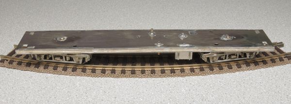
With the washers, it can handle very tight curves (approx. 350 mm radius), at least on flat ground.
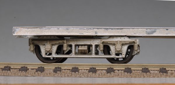
Same thing, in profile view. You can see that it is flush with the chassis. A little more would not be too much.
Three-point suspension
The manufacturer did not provide for a three-point suspension. However, I consider it necessary. First, the final distance between the chassis and the bogies must be decided, which, as we have seen, should be at least 5.4 mm (4 mm original + 1.4 mm raised) to allow for curve travel.
Single-point suspension: ball joint
As already done on Res Jouef wagons, I use a ⌀ 5 mm hollow brass bead cut to obtain a spherical cap. The inner diameter of the bead is 3 mm, which I increase to 4 mm so that it can fit onto the shoulder of the pivot. The height of the cap is 2.9 mm.
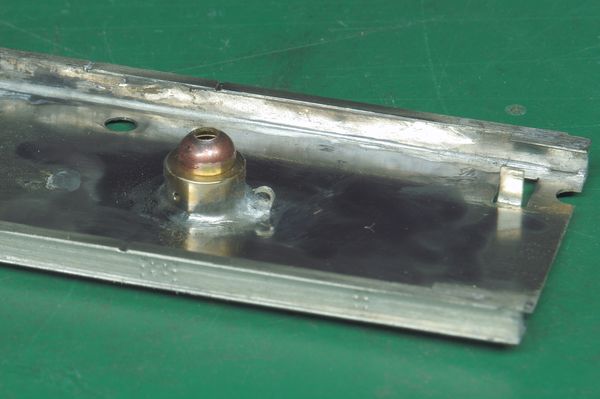
The bogie is simply placed on this ball joint: there is no need for a recessed counter ball joint.
To allow for proper movement and locking of the pivot screw, a small ⌀ 3, 0.5 thick washer is inserted between the screw and the ball joint.
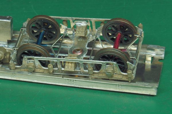
Two-point support
On the bogie chassis, the support consists of two ⌀ 4 mm brass tube segments ① soldered with tin-bismuth. Under the van chassis, two spacers ② are glued with thin double-sided tape, which allow them to be easily changed if necessary. They are 1.4 mm thick.
To ensure that the bogie is centred and its screw is locked, a brass ring ③ with an external diameter of 4 mm, an internal diameter of 2.1 mm and a height of 2 mm has been turned from a brass rod. It is in fact an extension of the original pivot.
Here is the profile obtained with this three-point suspension. The floor height is 15.5 ± 0.1 mm — instead of 14.7 mm to scale, as I mentioned earlier.
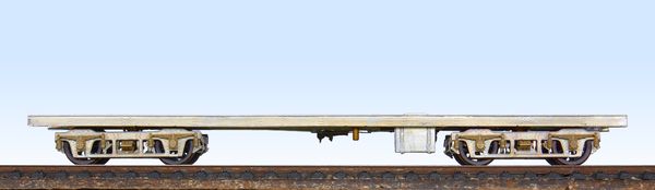
Move your mouse over the photo to see more details.