Construction of the L’Obsidienne  road roller (6)
Page created on 13/08/2025.
Doing and undoing…
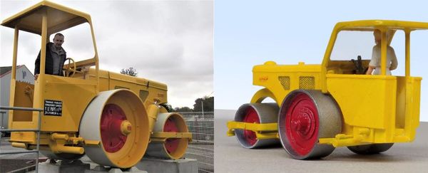
Or rather, in this case, undoing and redoing… While publishing the page dedicated to this machine, and comparing it with the actual photos, I noticed flaws that should have been obvious to me much earlier:
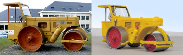
- The front roller is one millimetre too small in diameter! In fact, I used a ⌀ 12 tube, but, due to an aberration that I will try to explain, I turned it to ⌀ 11 on the outside, when I should have bored it on the inside and left the outside diameter unchanged. Explanation: mimicry with the machining of the rear wheels, from 16 to 15 mm; an alarm should have gone off in my head! Anyway, I did not have a boring tool.
- Another detail is glaringly obvious when compared to the real thing: the position of the roof support uprights, which should be much closer to the outer edge of the cab, since in reality it is made of relatively thin sheet metal. Here, the explanation is that I foolishly followed the manufacturer’s plan (even though I did not do so for many other details, go figure).
First of all, I had to dismantle the model; this was a risky task, but everything went well, including removing the cab roof.
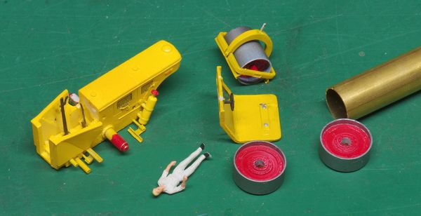
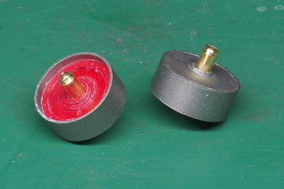
On the right, the pipe that will form the new front wheel rim.
New front wheel
As I did not have a tube of the right diameter, I ordered a ⌀ 12 × 0.5 brass tube.
Note that the seller offers a wide range of diameters and thicknesses.
The old ⌀ 11 tube is kept. I have no choice, since the resin part has been reduced to ⌀ 10. It is reduced to the inner width of the wheel, i.e. 9.7 mm; it is slightly turned to remove its paint and allow it to be inserted into the new tube, which is 14 mm wide. After carefully levelling the protrusion on each side, which is not so easy, the assembly is soldered with soldering water and a blowtorch. This operation is followed by cleaning the solder, degreasing, burnishing and finally painting.
I did not take any photos during this modification. Here is the front drivetrain reassembled. You can see that the wheel fits much better in the arch. You can see the old tube inside the new one.
You can also see that the arch is not perfectly symmetrical…
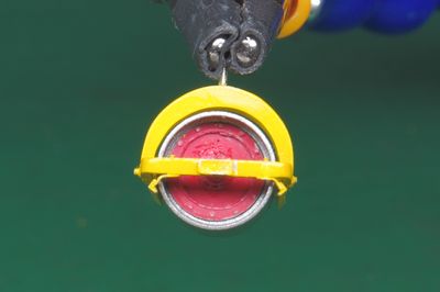
Replacing the rear wheel axle
When I mounted the rear wheel axle in the body, or the wheels on the axle, the paint on the axle was damaged. So I replaced the axle with two half-axles, each of which will be mounted on their wheel from the front, the whole thing then being inserted into the body. This way, the paint will remain intact.
Modification of the cab
The resin body is drilled to ⌀ 0.8 in the corners, 0.8 mm from the rear and side edges. The distance between the two holes is 9.6 mm. Holding the part without damaging it is quite a feat. In addition, these holes will need to be slightly enlarged to allow the uprights to be positioned correctly.
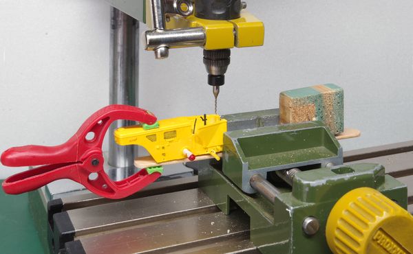
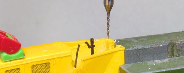
As for the roof, since I had to mill down the part that held the uprights in place and was soldered, I took the opportunity to try to reduce its thickness by about 0.8 mm. The operation was carried out in several passes, carefully, because white metal easily causes the milling cutter to jam, leading to overheating and the risk of melting; which is what happened!
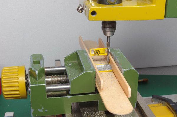
Click on the image to see the assembly more closely.
I should have removed the accessories before machining…
The result is not perfect, but I will settle for it, and the driver will no longer have his head stuck under the roof. It will also be easier to remove if necessary.
To attach the new uprights under the roof, I used the same method as before, with thin nickel silver plate drilled at 9.6 mm centres, to which they are soldered. The whole assembly is glued with Uhu Super. The difficulty lies in getting the position right in relation to the body, but this is made easier by the fact that this glue has a fairly long setting time.
Finally, I had to slightly mill under the nose of the vehicle with a half-round milling cutter to compensate for the increase in the front wheel diameter.
Painting the modified parts
Painting the modified parts (cab and roof) required masking the parts to be left intact with Tamyia tape. Painting on already decorated parts is obviously not very practical…
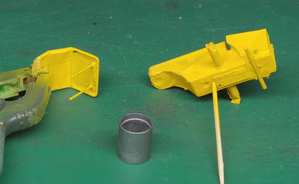
Note: the paint was redone before changing the rear axle, as described above.
Final reassembly
Reassembly required increasing the diameter of the pillar holes to 0.9 mm to account for the layer of paint that prevented them from penetrating the body.
At the end of this work, the appearance has been greatly improved, both for the front wheel and the cab.
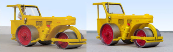
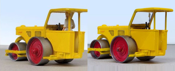
Before modification on the left. After modification on the right.
The height compensation at the front is perfectly correct, as can be seen in the photo at the beginning of this article.
Display case
Allright, I admit it is a bit of a vanity project! I simply copied* the Wiking Ruthemeyer roller case, which consists of a Bristol board interior and the case itself made of 0.25 mm transparent PVC.
- Not exactly: I placed the closure flaps on the long sides instead of the short ones. As a result, they are shorter and take up less space flat, so there is less material waste.
Here is the diagram for this case.
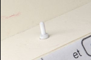
To hold the model in place, I used the ⌀ 1.6 hole drilled for the painting support, which I tapped with an M2 thread. I made a screw consisting of a threaded ⌀ 2 polystyrene rod and a knob made of the same material, with a diameter of approximately 10 mm, for ease of handling. This screw passes through the Bristol board base reinforced with a thick cardboard piece, and it is held in place by a nut also made of polystyrene.
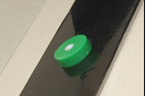
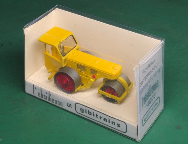
The driver and wheel weights are stored in the base.
Brass tube
OD 12 x ID 11 mm, length 300 mm
2,90 € (price 2026)
at aliexpress.com.