Construction of the L’Obsidienne  road roller (3)
Page created on 22/02/2025; updated on 08/03/2025.
Making new parts
Rear wheel axle
Here’s why the drilling for this axle is done at ⌀ 3. Larger shaft ends and their machining allow matching reality more closely.


Interesting advantage: this allows the optional fitting of ballasts, which remain removable. Unfortunately, this won’t be possible for the front wheel.

Note: the front axle will also deserve an increase in diameter.
Compressed air tank
This new cylinder is made from an ⌀ 2.5 Evergreen rod. In reality, the diameter should be more between 3 and 3.5 mm, but, on the model, it seems disproportionate to me, and too close to the rear wheel.
Fixing to the roller body will be done by two ⌀ 0.6 nickel silver pins.
On the tank body rounded off with a file on a mini drill, I added a ⌀ 0.8 nickel silver rod, and a flywheel made from a slice of plastic tube from a can of WD-40, whose diameter 2.1 has been reduced to 1.8 mm.

The tank supports are made from a polystyrene profile with a cross-section of 0.5 × 1 mm, milled according to the diagram, then cut to the correct length after gluing.
Here’s how the supports are being glued (using Faller Super Expert glue) to the tank fixed to a board.

Cut to length, tangent to the body.

The tank is strapped with two superimposed layers of self-adhesive copper tape cut into 0.5 mm wide strips.

Scrapers
These parts consist of an angle iron that rubs against the wheels and a different support, depending on whether the wheel is front or rear.
- Front scraper

The angle irons are supported by flat bars fixed to the wheel frame. To scale, the angle irons are made of 0.8 mm milled brass. The flat bars are made from 0.1 mm thick sheet brass, cut into 0.8 mm wide strips. The flexibility resulting from their thinness means that the position of the angles can be easily adjusted as close as possible to the wheel.
Soldering the supports to the angles.

Click on the image for a closer look to the parts.
The ⌀ 0.4 fixing holes are drilled 2.5 mm from the edge of the angle.

Click on the image for a closer look to the drilling.
Here are the parts made, before the length of the ends was equalised.

- Rear scraper
For the rear, the manufacturer seems to have wanted to produce a photoetched part, but it doesn’t look like much! You be the judge.


New parts are therefore required.
The support is also made of 0.1 mm brass sheet, but it is soldered onto a tube of the same material, ⌀ 1 × 0.6, which fits onto a ⌀ 0.6 nickel silver rod.
The end of the sheet is bent with flat pliers, then placed under the brass tube.

Click on the image for a closer look at the parts.
The two parts are soldered together…

… then the angle iron.

The parts are cut to length, then the ⌀ 0.6 nickel silver pin is soldered into the tube.
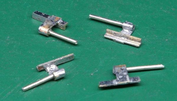
Here’s a quick blank test, which reveals that one of the scrapers (top left in the photo) is too short. This fault is remedied by unsoldering the angle iron and moving it away from the axle.

Adjustment is very simple, using the pivoting and depth of the pins.
I started fitting the front scrapers to the part I call the front wheel frame. Here is how it looks…


… and I don’t like it! This piece of white metal is decidedly coarse: its cross-section is 1.3 × 2.5 mm, when it should be 1 × 1.5 mm — give or take. I decide to remake it in brass.