Page created on 23/09/2025.
Working on the pantographs
This simply involves removing the central mounting for the pantographs and limiting their extension.
Removing the pantograph mounting
To access the pantograph mounting, after lifting the body, you need to remove the grey plastic covers which, I assume, contain the pantograph servomotors for models equipped with them. This gives access to the pantograph screw (M1.4). The insulators remain attached to the body. The pantographs are easy to remove, just be careful with the roof line and the jack rod.
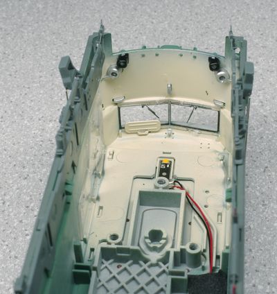
View from the inside once the grey covers have been removed.
Here is the body without its pantographs. The problem is that the mounting bracket is moulded with the body, rather than being a separate part as LS Models has done on some of its products.
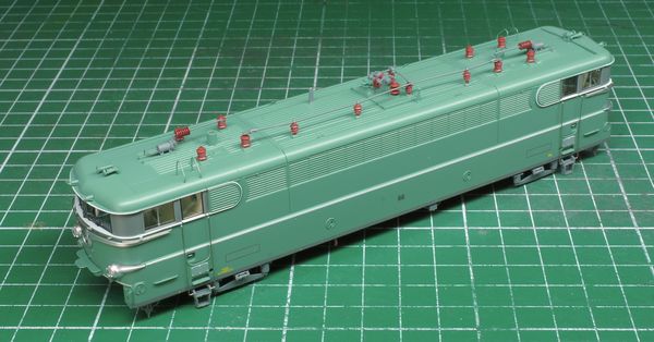
Click on the photo to see the bracket more closely.
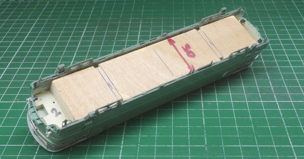
This protrusion will therefore have to be removed by milling ø 3. To do this, I insert a 150 × 30 mm plywood wedge into the body, with notches to allow the chassis mounting clips to pass through (distance 82.5 mm, width 4 mm). This allows the body to be clamped in the vice without risk of damage.
My ø 3 milling cutter has a dovetail shank, which leaves a conical section that I have to remove with a drill bit. Depth: approx. 0.5 mm.
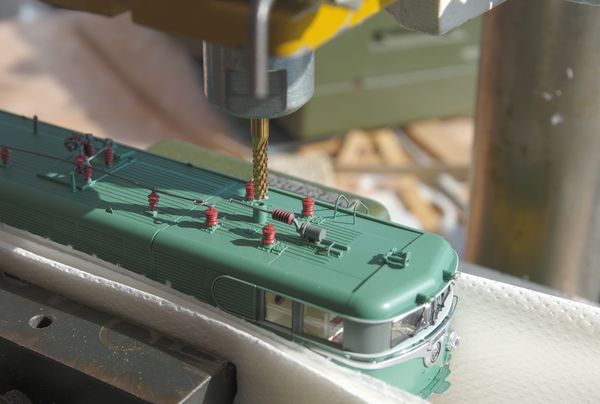
Click on the image to see the machining process in more detail.
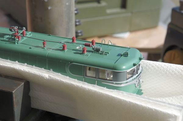
Click on the image to see the machining process in more detail.
I fill the remaining hole with a 0.3 mm polystyrene cover, cut out with a 2.5 mm diameter punch, and glued with Faller Super Expert.
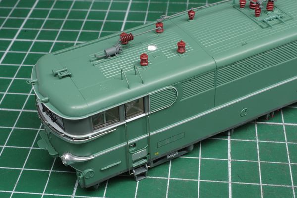
Click on the image to see the filling more closely.
Painting: I do not have any light bluish green at the moment. I make a clever mixture with Humbrol white acrylic and cyan, yellow and black ink-jet inks. The result is not perfect, but it is almost invisible.
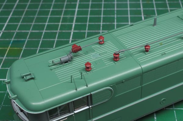
Click on the image to see the camouflage more closely.
Finally, the pantographs are glued to the insulators using Kristal Klear.
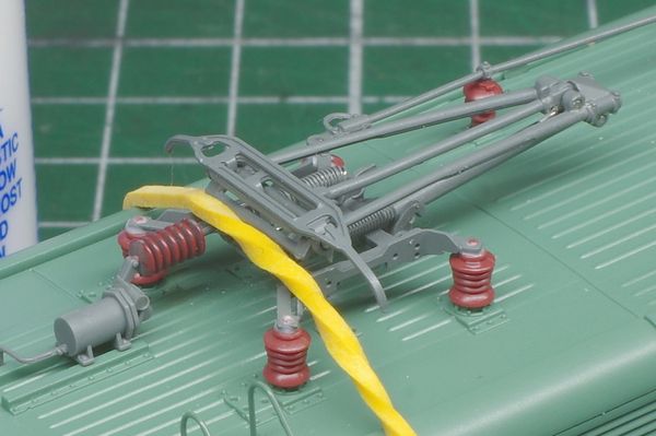
Here, I made a small mistake: I placed the roofline above the pantograph chassis, when it should be below it: the collar of the insulator in question is reduced for this purpose. This error has since been corrected.
Shim for limiting extension
As with all electric locomotives, the pantographs extend too far when free. This needs to be limited, both for aesthetic reasons and to prevent them from catching under bridges, for example.
A small Evergreen shim approximately 0.3 mm thick and 0.5 mm wide is placed in front of the spring attachment. Consequently, the spring must be removed for this operation. The shim is glued in place with CA glue. The photo was taken before painting in grey and putting the spring back in place.
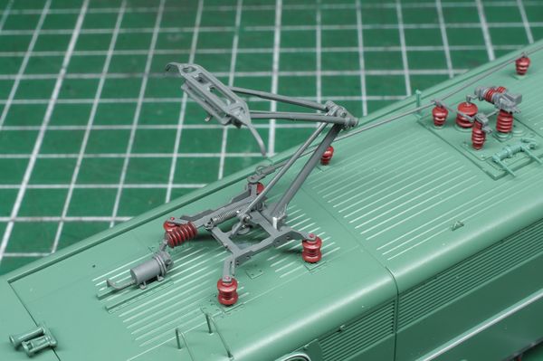
Click on the photo to see the shim more closely.
Reassembling the spring was complicated due to the extra thickness of the shim. I had to bevel it.
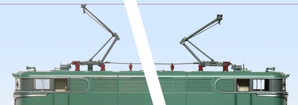
Comparison before/after limiting extension. Note the disappearance of the central attachment.