Page created on 23/09/2025.
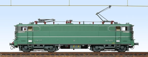
REE BB 16019 after modification.
Presentation
The locomotive is delivered with a complete buffer beam (including the lower drawbar attachment) and a buffer beam with shortened brake couplers and electric jumper. It is a pity about the latter, as it would not interfere with the swing of the NEM housing.
Two other buffer beams, one complete and one “shortened”, are included in the spare parts bag, which also contains:
- a photo-etched plate comprising three BB 16019 side plates and three SNCF plates;
- a photo-etched plate comprising three manufacturer's plates;
- a windscreen wiper;
- a lower traction attachment;
- an antenna;
- a NEM box;
- two loop couplings.
The machine is very detailed: there is even a representation of the Jacquemin transmission.
The handrails on the cabs are very thin (ø 0.3) but do not fit well into the steps. One has already come out of its housing.
The pantographs are the best single-leg ones I have seen, except perhaps for the stepped tubes of the upper frame, which are slightly less fine than the LS Models’. I note in particular that, for the first time to my knowledge, the bow link is articulated on the lower link, as in reality, and not on the main leg (an easy solution for manufacturing). I have only one criticism: their central screw attachment.
On the other hand, the folded retaining system is quite discreet: a small hook in line with the bow “lever”.
The circuit breaker block on the roof is slightly crooked. The HOM disconnector is inserted.
An embarrassing photo
Side view showing that the buffer beams are unfortunately sloping downwards.
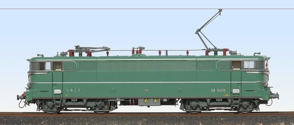
Click on the photo to see the buffer beam more closely.
First tests
In order to measure the diameter of the wheels, I had to dismantle an axle. When reassembling it, I found it difficult to reposition the pickup strips correctly. After putting it back together, I checked the continuity: there was a fault on one side, even on the bogie that I had not touched!
The cause is that the contact area on the inside of the wheel flange is very narrow, due to the plastic wheel flange.
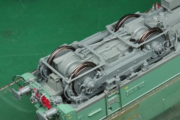
Nevertheless, the detail of these bogies is impressive: Jacquemin transmission, braking equipment, etc.
Electricity
Consumption
Consumption at 12 V DC is 380 mA in forward mode and 300 mA in reverse mode at slipping, before running-in. It rises to 1.2 A when the motor is blocked.
Appearance of the printed circuit board
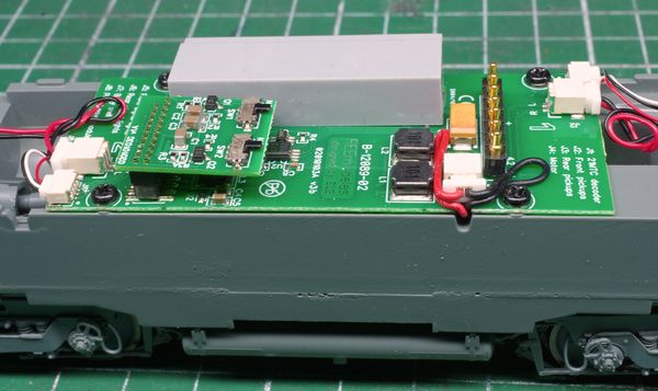
Click on the photo to see the dummy more closely.
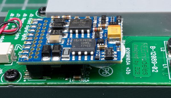
Zooming in on the dummy circuit (21-pin MTC interface) reveals two slide switches, each of which can be used to turn off all the lights at one end. The aim is to allow analogue operation with the lights off on the coupled end.
Installing the decoder is straightforward. Here is what it looks like with an ESU Lokpilot V4.0.