Page created on 21/03/2026; updated on 23/08/2026.
The observation
For car lighting, it is worth using conductive bearings (or bogie sides) in combination with insulated half-axles and non-insulated wheels. I have done this on numerous occasions: DEV REE, Express and Rapides from LS Models, etc.
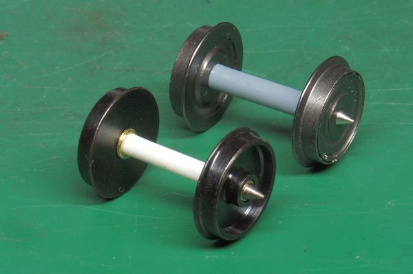
One drawback of this technique – which is, incidentally, far superior to having the current pickup strips rubbing against the axles, or, worse still, against the wheels themselves – is the need to join the two parts using an insulating sleeve. The diameter of this sleeve, at least 3 mm and sometimes up to 4 mm, is excessive compared to the actual 1/87 scale, which is closer to 2 mm. Here are some examples.
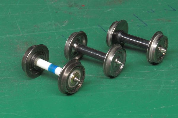
From rear to front: Hornby-Jouef on DEV Inox (sleeve diameter 3.5 mm), Rail Europ Express on B4D Sud-Est (3.0 mm), personal work on Express Nord LS Models (2.8 mm).
Sometimes this sleeve requires details of the bogies, such as the brake linkage, to be milled away.
R37 innovated by reducing the axle diameter to 1.5 mm. However, its sleeves are also 3 mm wide. It turns out that Evergreen offers polystyrene tubes with an outer diameter of 2.4 mm and an inner diameter of 1.2 mm. This brings us closer to the scale dimensions. I wanted to try using this tube as a sleeve. The concern is that this rather soft material might not be strong enough to hold the axles in place. That is what we are going to find out.
Manufacturing
Custom wheels: machining of conductive rings
Let us take as an example the wheels intended for my hypothetical Nord van, purchased a long time ago from Micro-Modele, which have a running diameter of 12 mm. They are all insulated on the axle by a ring with the dimensions given oppositebellow. The task is therefore to replace this ring with an identical one, but made of brass.
Of course, the difficulty lies in ensuring that the brass sleeve is tightened just right – neither too tight nor too loose – whereas plastic is more forgiving in this respect. So there is quite a bit of waste! I have already described the manufacturing process in another article, so I will not go into it again here.
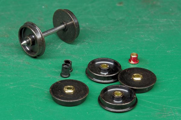
In the background, the original axle with its two insulating rings. In the middle, two removed insulating rings. On the right, marked in red, a failed brass ring, and in the foreground the four fitted wheels.
Axle shaft
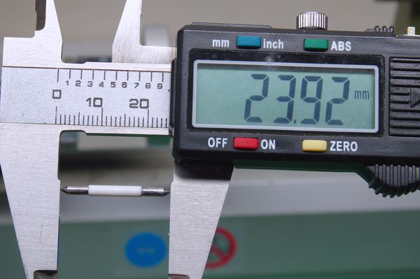
The shaft design is based on a length between tips of 23.8 mm, in accordance with NEM 314 (23.9 ± 0.1).
The length of the ends that receive the wheels, left at their original diameter, has been determined through successive trials to be 6 mm. If it were any shorter, it would not fit correctly in the chuck of the lathe used for machining. However, the ideal length would be 5 mm: the shoulder would then be flush with the wheel hub.
Machining in pictures
- marking and cutting the shaft into two equal parts (not shown);
- marking the half-shaft 6 mm from the tip, depth 0.1 mm (any deeper and there is a risk of breakage at the notch — it has happened);
Click on the photo for a close-up view.
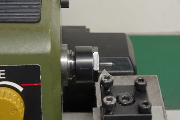
- turning the workpiece over and positioning the previous groove flush with the ER collet, to achieve the longest possible span;
Click on the photo for a close-up view.
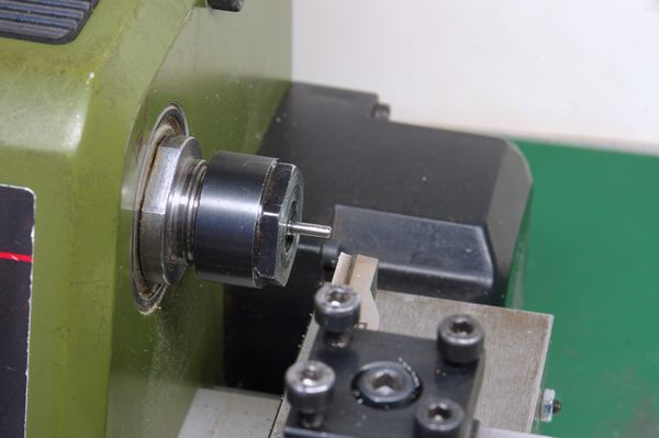
- turning in 0.1 mm increments; from a depth of 0.3 mm, in 0.05 mm increments, up to the mark;
Click on the photo for a close-up view.
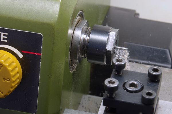
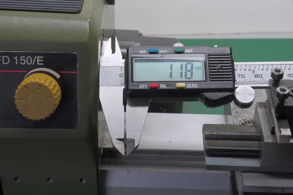
- diameter check (to be carried out during machining);
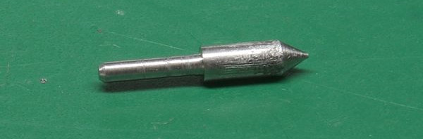
- length adjustment and filing of the end (not shown). Finished half-shaft.
- sleeving of the two axle halves. A slight adjustment to the length will probably be required when fitting them to the receiving vehicle. This length nevertheless complies with NEM 314 (23.9 ± 0.1).
Tool for fitting the wheel onto the axle
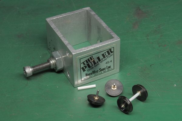
To fit the wheels onto their axles, I use the Puller as a Pusher! To do this, the wheel rests on the Puller’s frame, and the axle is pushed into the wheel via a brass piece with a tapered end to accommodate the axle tip.
It is different here, as the half-axle no longer has a tip. Furthermore, it is weakened by the reduction in its diameter and bends very easily. It is therefore no longer a question of pushing on its end, but, using a suitable tool, on its shoulder.
Here are the dimensions of this tool.
Note: the bore is 1.4 mm, not 1.2 mm. In the meantime, I have found some ABS tubes that are slightly stiffer than the Evergreen ones and have an internal diameter of 1.4 mm. This also means the half-axles do not need to be machined as deeply.
Assembly
Positioning the tool and the half-axle in the Puller.
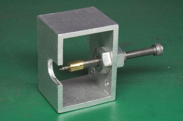
Inserting the axle into the wheel.
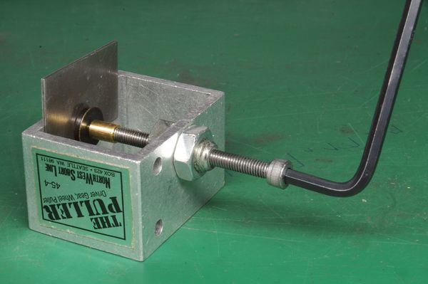
Side view.
Click on the photo for a close-up view.
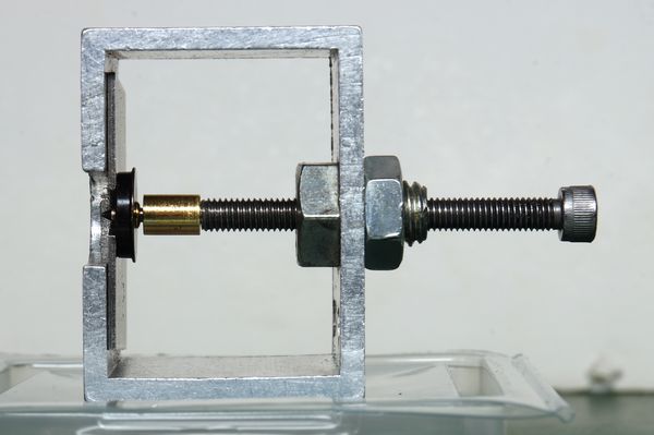
A test run with the wheels prepared as described above shows virtually no wobble.
In the background, an R37 axle for a cement wagon, with the axle shaft reduced to 1.5 mm and the sleeve exactly 3 mm in diameter. This is, however, the smallest diameter found on commercially available products using this technique; see above.
I have noticed that the R37 sleeve is very off-centre: the bore is neither coaxial nor parallel to the outer cylinder; but the important thing is that the axle halves are aligned. The Evergreen tube is much better in this respect.
Trying out a simpler solution
This solution stems from the following line of thinking.
Reducing the diameter of the shafts by turning is time-consuming and requires numerous checks during machining. Why not use smaller-diameter axles directly – ⌀ 1.5 in this case – in combination with ⌀ 2 × 1.1 ABS tubing (I couldn’t find any in 1.5)? But it turns out that the tubing I bought has an internal diameter just under 1.5, which is perfect.
Question: are there any ⌀ 1.5 tip-bearing axles available? Wheels mounted on this type of axle are available from Micro-Modele, but they are expensive, and I don’t need the wheels, as their diameter is too small. It should be noted that a diameter of 1.5 mm is the NEM standard for the TT scale, for which the axles must be 18.5 mm long – which is too short. As a result, I’ve had to resort to using piano wire: I have to fall back on piano wire: its main drawback will be the need to machine the tips.
Objection: but you’ll also need wheels bored to ⌀ 1.5, whereas the standard is ⌀ 2. I’ll reply that I have to machine conducting rings to replace the insulating ones. Consequently, boring them to 1.5 instead of 2 won’t make any difference.
Preparing the axles
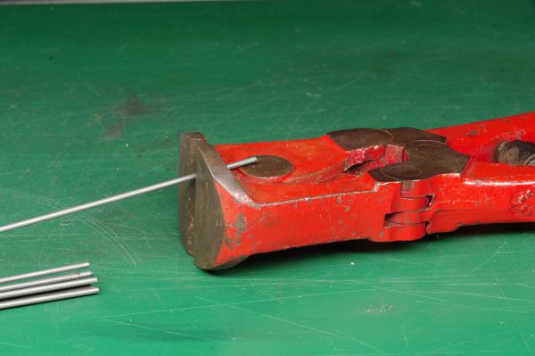
- Cut 13 mm lengths of piano wire using a lever-action wire cutter or a cutting disc.
- Trim the first end using a diamond disc, by hand, then chamfer it slightly at an angle of approximately 45°.
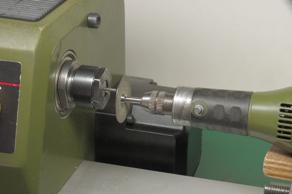
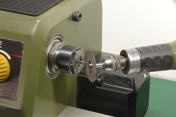
- After measuring the length to determine how much material remains to remove (the target net length is 11.5 mm), turn the workpiece over and dress the second end. Check its length.
NB: the length does not need to be highly precise, but it is better to have it slightly shorter than slightly longer: you must ensure that the two future half-shafts do not touch each other…
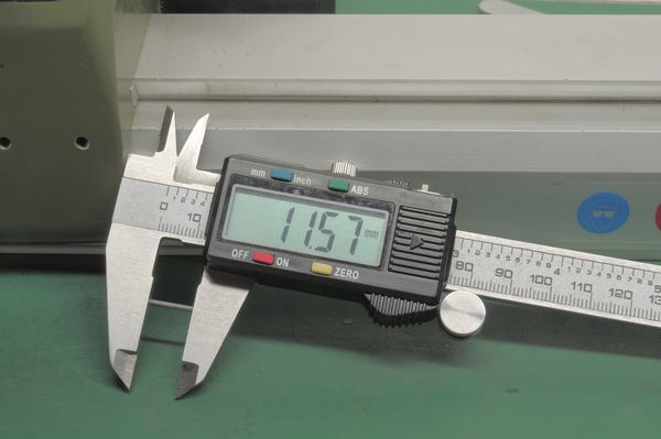
- Machine the tip, still using the diamond disc, following a line drawn on a self-adhesive label. The total angle is 50° (NEM 314: < 55°). But I find this is still too much. 45° seems better to me. Rounding and finishing are carried out using 600-grit abrasive.
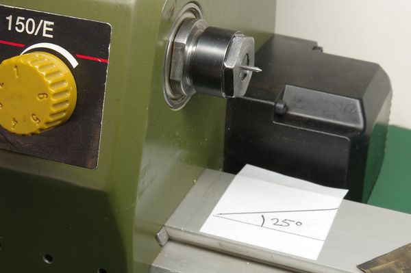
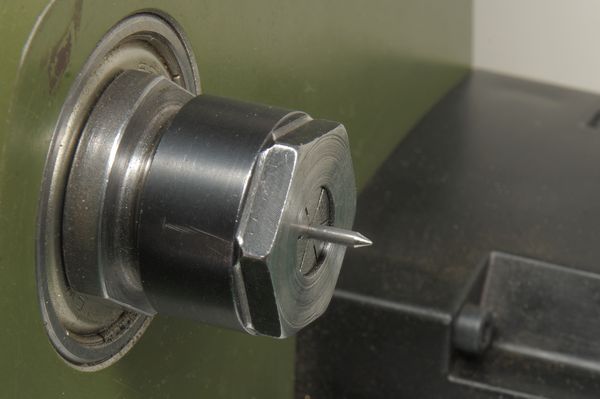
A close-up view shows the rounded tip. On closer inspection, the cone could do with a proper polish; otherwise, watch out for wear on the axle boxes!
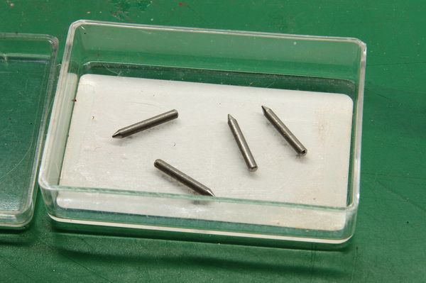
Here are four finished half-shafts, to fit two axles.
Conductive rings
I will not go into that again. Do note, however, that when bored out with a 1.5 mm carbide drill bit, they fit onto the piano wire spindle quite loosely, but tightly enough.
Fitting the half-shafts
The sleeves made from the new ABS tubing have an external diameter of exactly 2 mm. However, the internal diameter, stated as 1.1 mm, actually varies between 1.3 and 1.5+. Some sections are too loose and must be discarded; others are too tight and split during fitting. This is, however, quite rare.
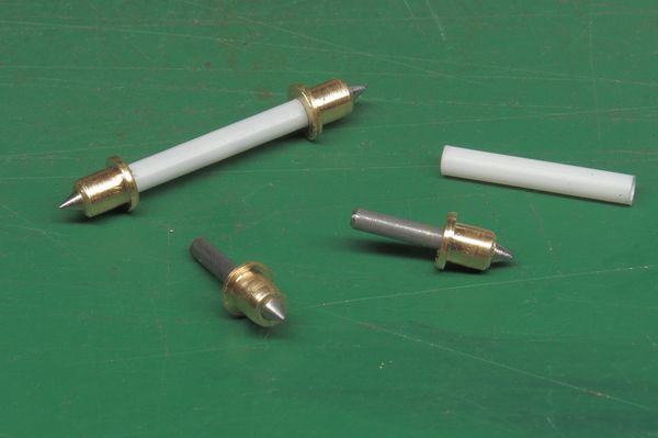
Fitting the wheels
The wheels are fitted using the Puller, as before. As the rings have a bearing diameter between 2.79 and 2.81, the tightening is very satisfactory.
Click on the photo for a close-up view.
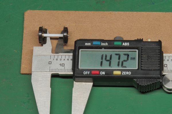
Here are the key dimensions for an axle before adjustment. The back-to-back distance between the wheels (NEM 314: 14.4 ± 0.1), which is 14.7 mm, is adjusted by shortening the sleeve by 0.3 mm. The distance between the wheel tips (NEM: 23.9 ± 0.1), which is 23.4 but has been reduced to 23.1 due to the shortened sleeve, is corrected by moving the half-axles within the wheels by 0.4 mm on each side.
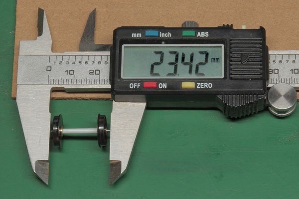
I have finally achieved the result I was looking for: axles that are insulated in the middle, whilst still having the correct shaft diameter.
In conclusion
One might well wonder whether such a degree of fiddling is worth it for a result that will hardly be visible once the axles are fitted. I have been asking myself the same question. My answer: it is an option that should not be applied across the board, but used on a case-by-case basis. And anyway, I have so much fun with my lathe!
Tube diameter 2.4 mm
Pack of 8
Ref. 269-PS-423, €12,50
at micro-modele
ABS tubes ⌀ 2 × 1.1, L = 25 cm
Pack of 5
Ref. 1005008174842052, €2,60
at Aliexpress
Piano wire ⌀ 1.5
Length 1 m
Ref. Cordeapiano-1,5, 0,90 €
at micro-modele