Page created on 02/10/2025.
New coupling drawbar
As with my Roco trailers and my Picasso Mistral, I want to be able to attach the REE trailer without removing the skirt under the buffer beam. The idea is to make a flat brass drawbar that fits under this skirt.
Feasibility study
The aim is to check whether it is possible to install such drawbars given the limited space between the skirt and the bogie, while making as few modifications as possible to the existing parts.
I therefore need to take fairly precise measurements, the results of which are shown below.
The original drawbar (coloured cyan) clearly interferes with the lower skirt ; that is why the latter must be removed, to the detriment of aesthetics.
Let us now see what can be done. Click on the image to see the draft of the new drawbar. At first glance, the only interference it will have will be with the front crossbar of the bogie.
There are two options for holding the coupling head:
- either a NEM 363 standard head bracket (box […] in case of lack of space);
- or pins (connector pins for printed circuit boards), as I did for my Picasso Mistral.
I will try both, knowing that the first has the advantage of being more universal, but the disadvantage of being more difficult to make.
Bracket for NEM 363 head
Manufacturing
From a 0.5 mm brass sheet, I cut out a 25 × 4 mm rectangle — the length, which is slightly longer than that specified in the plan, will be adjusted at the end of the manufacturing process. A ⌀ 1.2 milling operation is carried out…
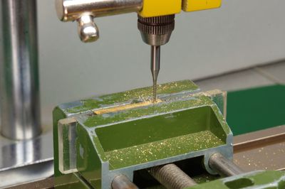
Click on the photo for a closer view.
… Then the curves are made slightly square with a quarter-point file.
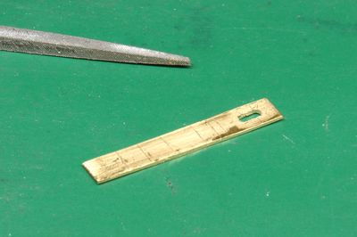
Click on the photo for a closer view.
Folding is not so easy when it comes to respecting the dimensions. From the first fold, I check that the swing is correct.
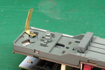
Folding completed.
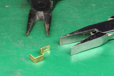
Now comes the most difficult step: making the dovetail bracket as shown oppositebelow, using 0.2 mm nickel silver, which is fairly rigid.
Folding is easier if you start with slightly oversized wings (2 mm instead of 1.4 mm) to make it easier to grip with the pliers.
Soldering on the drawbar with tin-lead after tinning; the parts are held together with crossed tweezers.
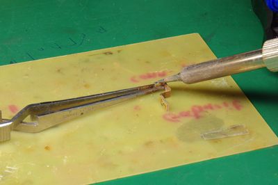
Click on the photo for a closer view.
Note the plate reinforcing the drawbar mounting lug. For this first test, it is 0.5 mm thick, which proved to be too thin to hold the drawbar securely in place. The next one will be 1 mm thick. The ideal thickness would be 1.5 mm.
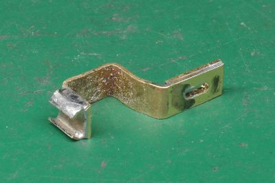
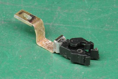
Fitting a Fleischmann ProfI head. In all honesty, I have to admit that I made three attempts, some too wide, some too narrow, before achieving this satisfactory result. This is one of the reasons why I will ultimately use the second solution.
Work on the bogies
As expected, the bogie’s front crossbar needs to be cut, but only over a short length. I find the result quite discreet. Note that the brake shoe connecting bar is not affected. The bogie in the background is intact.
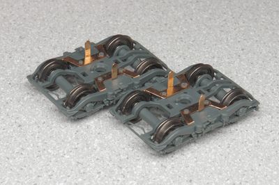
Click on the photo for a closer view.
Tests
The drawbar fits well under the body (with plenty of play) and is slightly further away from the crossbar than expected (1 mm instead of 0.5).
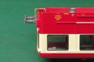
Note that this test was carried out before soldering the NEM 363 bracket.
Coupling test with the Mistral Picasso equipped with a pin coupling bracket.
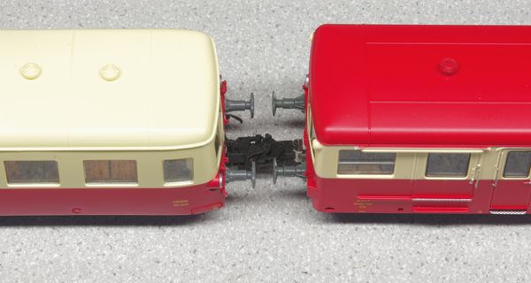
The buffers are clearly too far apart. The close-up view shows that the trailer is largely responsible for this. All the more reason to opt for the second solution.
Bracket based on printed circuit board pins
The manufacturing process is similar to the previous one. There is one less fold and two additional ⌀ 0.8 holes.
Manufacturing
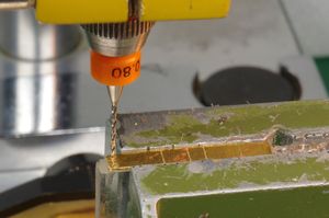
Drilling of ⌀ 0.8 holes spaced 2.54 mm apart at the end of the drawbar to accommodate the pins.
Soldering of reinforcement plates on the rear section.
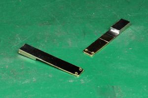
Milling the rear section, starting by drilling two ⌀ 1.2 holes to 1.7 mm apart according to the plan, followed by the actual milling in 0.25 mm passes, and finally squaring off with a file.
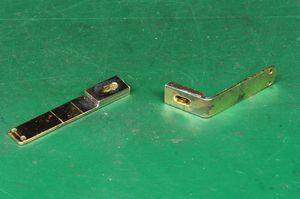
One of the drawbars was folded to check that it fitted onto the trailer support.
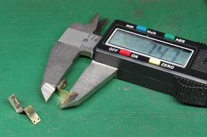
Folding. The adjustment was made on the vice with a small hammer. This allows me to correct a misplaced fold quite easily. The height obtained is a little too high: 7.5 instead of the expected 6.8. Better too much than not enough…
Soldering the pins after adjusting their protrusion to 4.5 mm.
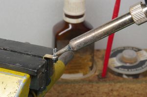
Click on the photo for a closer view.
Trimming the pins under the drawbars and removing their insulating support.
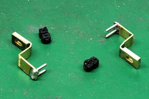
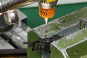
Drilling the ProfI heads held in the vice using a NEM Ribu housing.
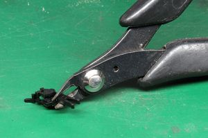
Removal of the ProfI tail.
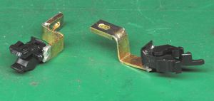
Mounting of the prepared ProfI heads on the drawbars.
Tests
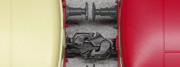
The coupling with the Picasso is significantly shorter than before, even though the buffers do not yet touch.
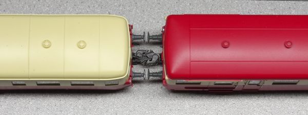
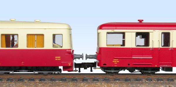
Coupling seen closer up:
Side view showing the correct height of the coupling, which I did not need to adjust, purely by luck.
Finally, a run on my Fleischmann test track, featuring curves with a minimum radius of 356 mm, went smoothly, both in traction and reverse.
Testing a rigid coupling bar
The current distance between the pins on the two vehicles is 13.5 mm. The gap between the buffers is 2.5 mm. If you want to eliminate this gap completely, you can replace the coupling heads with a simple bar with four holes, which will be placed over the pins.
The shape shown is only a suggestion.
It turns out that this bar (for the test, a simple rectangle cut out of a CD case) is difficult to install. It is up to each individual to decide whether it is worth the effort.
Personally, I find the lowered position of the bar rather inelegant…
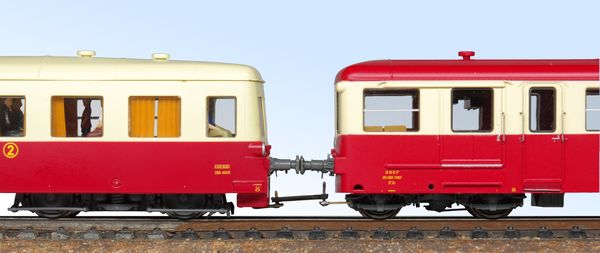
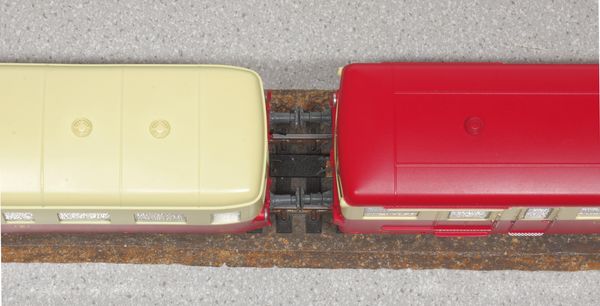
Conclusion
All that remains is to apply a coat of grey paint to the drawbars. I think I will secure them with a drop of Kristal Klear glue, as they have quite a bit of vertical play. This way, it will still be possible to replace them with the original parts, which will be useful if my heirs ever decide to sell the vehicle…