Page created on 26/09/2024; updated on 10/09/2026.
Electric circuits and lighting
Preliminary study
In preparation for the new wiring, I carry out a fairly accurate reading of the chassis dimensions. This is to avoid any unpleasant last-minute surprises!
- Worm gear cover.
- Motor.
Space available above the chassis
After measuring various heights (inside of body: 29.0; middle of chassis: 25.5; sides of chassis: 23.5), I deduce that the minimum space available is 3.5 mm.
There is plenty of room for a PCB. The most bulky components, the energy storage capacitor and interference suppression inductors, will be mounted underneath, along with the 21MTC connector: there is a space of at least 30 × 16 mm between the motor and the bogie transmission. The ESU Lokpilot 5 decoder just fits in the width. It would be more practical above, but it would need a clearance of 10 mm, which isn’t the case.
Printed circuits boards
There are five PCBs in all:
- the main circuit, which contains the decoder, the LED resistors, the LC interference suppression circuit, etc.;
- two circuits for the lights;
- two for cabin lighting.
These circuits are shown here in front of the stripped locomotive chassis.

Here are the fitted circuits, starting with those for the lamps and cabs.

The main circuit, recto.

Notes
- The connectors for the cab circuits are very exposed because they are too close to the edge of the board. This needs to be corrected!!
- The numerous fixing holes show that I had some difficulty in finding the ideal position for the circuit on the chassis!
Verso.

For the moment, I’ve fitted a 470 µF capacitor. It will be possible to install a 1000 µF / 25 or 35 V capacitor.
First tests
Here’s how the decoder is programmed:
| Key | Effect |
|---|---|
| F0 | Reversible white lights |
| F1 | Reversible red lights |
| F2 | Reversible cab lighting |
| F3 | All white lights |
I have two problems:
- The loco moves in the opposite direction to the lights. I thought I’d correct it with CV27, bit 1 = 1, but no: everything is reversed, lights and motor, so the problem remains. I have to swap the motor wires. I would have liked to change the red wire for a grey one, but I couldn’t dismantle the motor, whose housing is firmly clipped into the chassis. I just put a piece of grey heat-shrink tubing over it. As for the black wire, which is accessible, I swapped it for an orange one.
- Cabin end 1 doesn’t light up. I have to say that I used the AUX3 and AUX4 outputs unamplified. So I might have had some doubts about the operation of wiring LEDs directly to them. But, in fact, it was just a bad solder joint on the AUX3 pin of the decoder connector.
Fitting the lamp circuits
When designing the PCB, I determined the height of these circuits so that they would rest on the chassis. The old bulb holders had to be milled a little to give them sufficient clearance (hatching).
The photo below was taken after fitting the Evergreen circuit supports discussed below.

Black — but in white on the drawing — polystyrene masks, taken from a CD case, are used to prevent light leaks. Here are their dimensions. The legs will be inserted into the chassis recesses that receive the buffer tails, which will need to be slightly shortened.
The total thickness with the PCB is 2.2 mm.

Circuit supports are made from a 2 × 0.5 mm Evergreen profile. They are glued into the recesses with a two-component epoxy adhesive.

Note the milled moulding of the old bulb support. The new supports and this milling are aligned.
To reinforce the assembly, pieces of Evergreen with a cross-section of 2 × 1 mm are glued into the recesses: by compensating for the thickness of the PCB, they increase the gluing surface of the whole assembly.

And here is the complete assembly.

Finally, an overview of the wired circuits.

A rather belated idea…
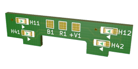
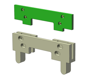
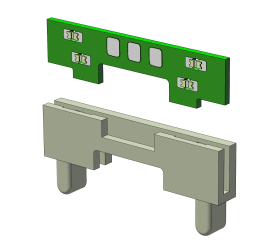
Two years later — and therefore too late — I thought of making a 3D-printed bracket for the light circuit. This one-piece bracket would hold the circuit securely in place, whilst avoiding the need to mill the chassis.
The drawings speak for themselves. The modified printed circuit board, shown in green, slots into the bracket. Grooves are provided to accommodate the LED bodies, which protrude slightly from the circuit board. In addition, an opening clears the way for the power supply wires to enter.
To be continued.
Samxon ref. EKM108M1EG16RRS0P
1000 µF/25 V, ⌀ 10 × 16.
€1.95 per 10, price 2024
at TME